Unidirectional Parallel Ports let us read and write to a device separately. How do we do both read and write to the same lines of a device? We can use the unidirectional parallel ports as a starting point and glue them together. Two variations are discussed here; one sets the direction of the lines at a given time explicitly, while the other one figures it out from the contents of the write-only register.
Explicit Bidirectional Parallel Ports
In the case of the explicit bidirectional port, we start with unidirectional read-only and write-only ports. Then, an additional register is added, the Data Direction Register DDR.
- Each line on the output side of this register is connected to the enable line of a tri-state.
- The input to the tri-states are connected to the corresponding bits of the
DOregister, and the output of each tri-state is connected to the bi-directional data line of the device.

Why does this work? Let’s think about a two-bit parallel port. It’s configured such that data is to be written in D[0] and read from D[1].
- The first step is to write
DDR = 01. This enables the tri-state on theD[0]line, while disabling the tri-state onD[1]. - Now that the port is configured, write a
1toD[0]. The CPU would write to the address ofD0with a value ofx1, wherexis a don’t care.- Since the tri-state on
D[1]is disabled, the data at the output ofD[1]is disconnected from the bidirectional line.
- Since the tri-state on
- To read the the data, the CPU would read from the addresses of
DI. When read, the data onD[1]will be whatever the device is setting it to, while the data on bitD[0]will depend on the contents of theDOregister.
What if we configured D[0] incorrectly as a write line while the device believed it should be driving it? We would have a conflict; safe operation requires that both sides agree on which lines are being written by the CPU.
It’s important to note that even though some lines have been designated to be written and others to be read, all transactions from the CPU perspective still have data for all data lines on the bus. Whether those bits are meaningful or not depends on the port settings.
Implicit Bidirectional Parallel Ports
Starting from the unidirectional write-only and persistent read-only ports, we again want to connect them to the same data lines coming from the device in such a way that there is no driver conflict.
In the implicit case, passive pull-up drivers are used to do this.
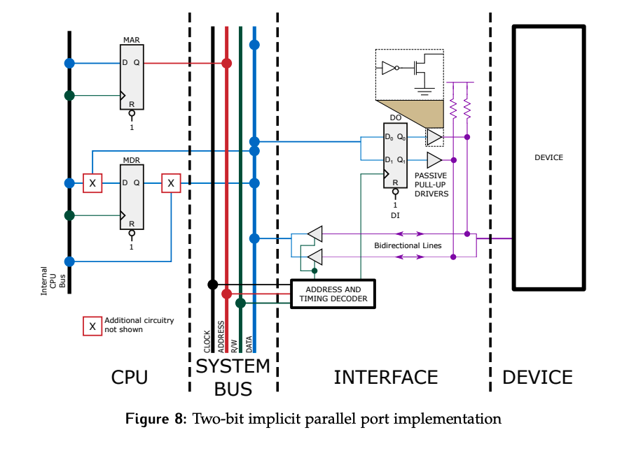
Consider the same case as above, where a 1 is to be written to D[0] and the port reads from D[1].
Recall the truth table for a passive pull-up buffer:
- If the input is a 1, the output is high impedance.
- If the input is a 0, the output is 0.
Since pull-ups have been connected to the data lines, writing DO = 11 will have the effect of disconnected D0 from the data lines and allowing the pull-up to drive D[0] to a 1 as desired. If we assume D[1] can be driven by the device, we can now read it as well.
The key is to understand that if bit 1 in D0 was currently set to 0, a 0 will always be read on this line, regardless of what the device was actually trying to set the value to. Furthermore, the device must use passive pull-up drivers on these lines; otherwise, there is the potential for bus conflicts if the device happened to try and drive an active 1 while D0 was set to 0 on the same line.
As such, the “implicit” name comes from the fact that the ability read a line is not controlled by a separate DDR, but by the contents of the DO register.