The general layout of a shaft to accommodate shaft elements, e.g., gears, bearings, and pulleys, must be specified early in the design process in order to perform a free body force analysis and to obtain shear-moment diagrams.
Typically, the geometry of a shaft is a stepped cylinder. The use of shaft shoulders is an excellent means of axially locating the shaft elements and to carry any thrust loads; each shoulder in the shaft serves a specific purpose, which we can attempt to determine by observation. The geometric configuration of a shaft to be designed is often simply a revision of existing models in which a limited number of changes must be made.
Axial Layout
The axial positioning of components is often dictated by the layout of the housing and other meshing components.
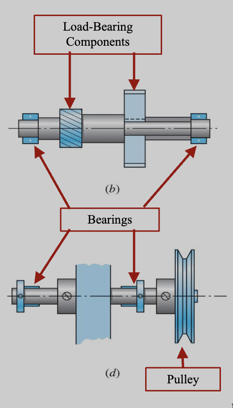
- In general, it is best to support load-carrying components between bearings. Thus, we should keep load bearing components close to bearings.
- Pulleys and sprockets are an exception to this, as they often need to be mounted outboard for ease of installation of the belt or chain.
- The cantilever (distance from bearings) should be kept short to minimize the deflection.
- Typically only 2 bearings are used, except with very long shafts.
- Keep shaft as long as possible; this minimizes the bending moment and deflections, although we still need to allow for lubrication and disassembly.
- We also need to consider connections between shaft and other components. This needs to be precise, which is often achieved by positioning components against shaft shoulders.
- In cases where axial loads are not trivial, it is necessary to provide a means to transfer the axial loads into the shaft, then through a bearing to the ground.
- Shoulders, retaining rings and pins can be used to transmit axial load to the shaft.
- Axial loading on only one bearing is desirable, as this allows for greater tolerances on shaft length dimensions, and to prevent binding if the shaft expands due to temperature changes.
Torque Transmission
The main purpose of most shafts shafts is to transmit torque from an input gear or pulley, through the shaft, to an output gear or pulley. The shaft itself must be sized to support the torsional stress and torsional deflection. It is also necessary to provide a means of transmitting the torque between the shaft and the gears.
A common torque transfer method is to use keys, pin, setscrews, and splines.
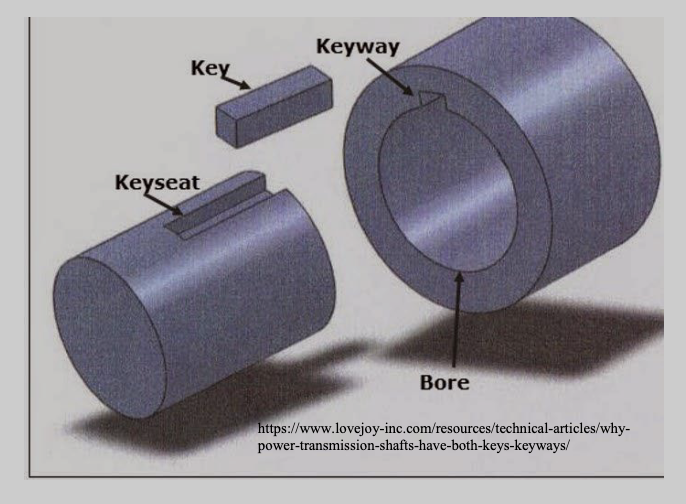
Keys
- Effective and economical for moderate to high torque
- Slip fit onto shaft for easy assembly and disassembly
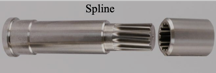
Splines
- More expensive than keys
- Typically used for high torques
- Can allow for axial motion while still transmitting torque
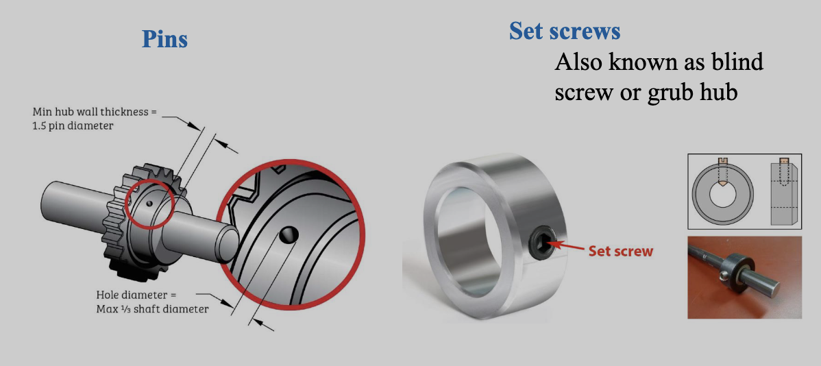
Pins and Setscrews
Common torque-transfer elements for low torques.
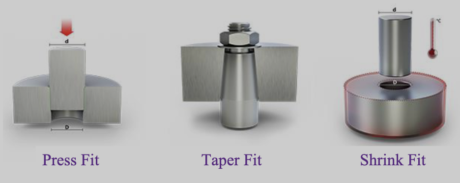
Fitting Torque-Transfer Methods
- Press fit:
- Transfer torque and preserve axial location.
- Shaft is larger in diameter than hole into which is pressed
- Shrink fit:
- Transfer torque and preserve axial location
- Hub is expanded with high temperature or shaft contracted with low temperature during assembly.
- Tapered fits:
- Often used on overhanging end of shaft.
- Fastener is tightened to draw parts together.
Assembly and Disassembly
- Assembly
- Largest diameter at shaft center and smaller diameters at ends
- If components need to be contained with shoulders on either side, one must be attached (e.g., retaining ring or sleeve).
- Shaft must fit within the housing (i.e., gearbox) and connect appropriately to the bearings within the frame.
- Disassembly
- Need to access components for removal
- Consider space needed for tools to assist with removal