For ferromagnetic materials, the magnetization process can be described as graphically. Consider a simple magnetic circuit. The magnetization curve results from drawing the variations of the magnetic force versus the magnetomotive force produced by the current applied to the coil.
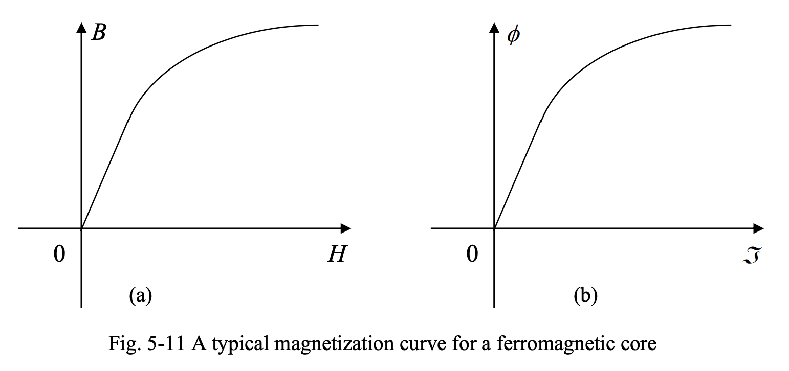
Based on the linear relationship between the magnetic flux and magnetic flux density (), and the linear relationship between magnetomotive force and magnetic filed intensity (), the plot of versus follows the same trend as that of versus , and is also called magnetization curve.
Some observations between ferromagnetic and non-ferromagnetic materials:
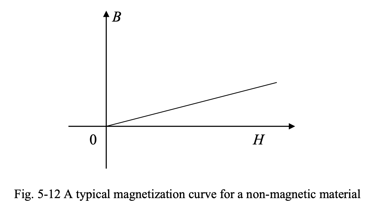
- The - curve of a non-magnetic material is linear. This implies a constant permeability () based on the relation .
- The slope of the - curve of a non-magnetic material is very small. This implies a small permeability (e.g., for air), and that a lot of effort form the magnetic field intensity, and thus the applied current, would be necessary to result in a small increase in the magnetic flux density.
- The - curve of a ferromagnetic material is nonlinear. Thus, based on the relation , the permeability () of the core changes with magnetic field intensity. The - characteristic of a ferromagnetic material is usually given in the form of a graph or a table.
- The slope of the - curve of a ferromagnetic material is very large. This implies a large permeability () and that a small effort form the magnetic field intensity, and thus the applied current, would be enough to make a considerable increase in the magnetic flux density.
- In the B-H curve of a ferromagnetic material, three distinct regions can be identified:
- Linear region, in which is constant and very large
- Saturation region, in which increasing does not result in a noticeable change in
- The knee of the curve, which is the region between the linear and saturation regions.
In ferromagnetic materials, a given magnetomotive force results in a much larger flux than in non-magnetic materials. In electric machines, the magnetic flux is responsible for producing an emf (in generators) or a torque (in motors); thus, we want to get as much flux as possible from the applied magnetomotive force. Machines are operated near the knee of the - curve to achieve high flux densities, while avoiding core saturation. The - curve is not linear in this region, making the analysis of electric machines somewhat tricky.
When an application calls for a linear - curve for the intended operating range, solutions such as limiting the excitation current and introducing an air gap in the magnetic core can be implemented.
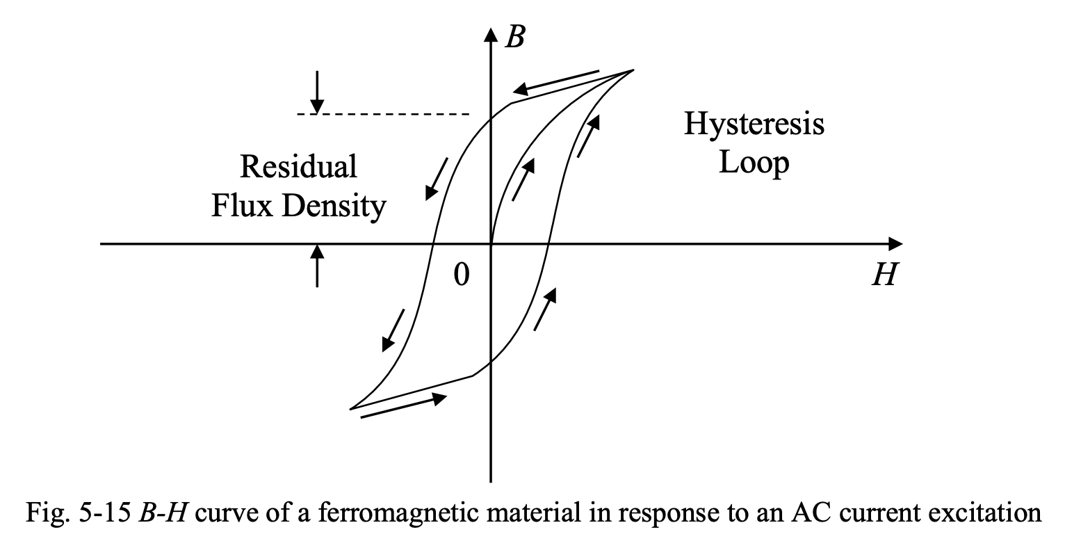
Hysteresis Loop
The area enclosed by hysteresis loop represents the energy lost in one cycle of AC current or excitation (or mmf). This is a loss, implying that part of the energy spent to magnetize the core in either direction is not returned to the source upon de-magnetization.
In electric machines and transformers, it is desirable to have a slim hysteresis loop (small area).
- The magnetic materials with this property are called soft materials. Using soft magnetic materials reduces the losses and makes sure that the changes in excitation current (or applied mmf) are followed quickly by the magnetic flux density.
- The materials used in permanent magnets or permanent-magnet machines, have a hysteresis loop of large area. The magnetic materials with this property are called hard materials. Using hard magnetic materials ensures a large residual flux density, making sure the magnetism is maintained when the excitation is removed.