Another problem that exits in DC machines is the voltages produced as a result of reversing the direction of current in armature conductors in the process of commutation. Current direction reversal causes high ; in the presence of inductance of armature windings, this results in high voltages at the commutator and brush assembly that can cause sparking and excessive wear to the related parts of the machine.
To solve this problem, additional poles, called interpoles, are used on the stator between the main stator poles.
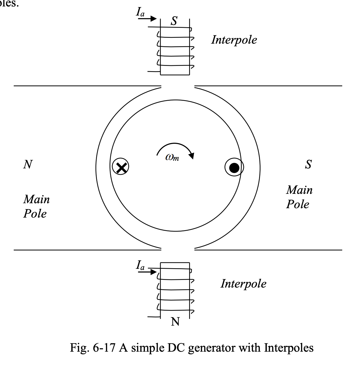
The armature current is used to produce a flux in the interpoles proportional to the magnitude of the current . When the loop sides leave the pole faces and the direction of their currents is being reversed, an voltage will be induced in them that opposes the change in the current in attempt to restore the original magnitude and direction of the current.
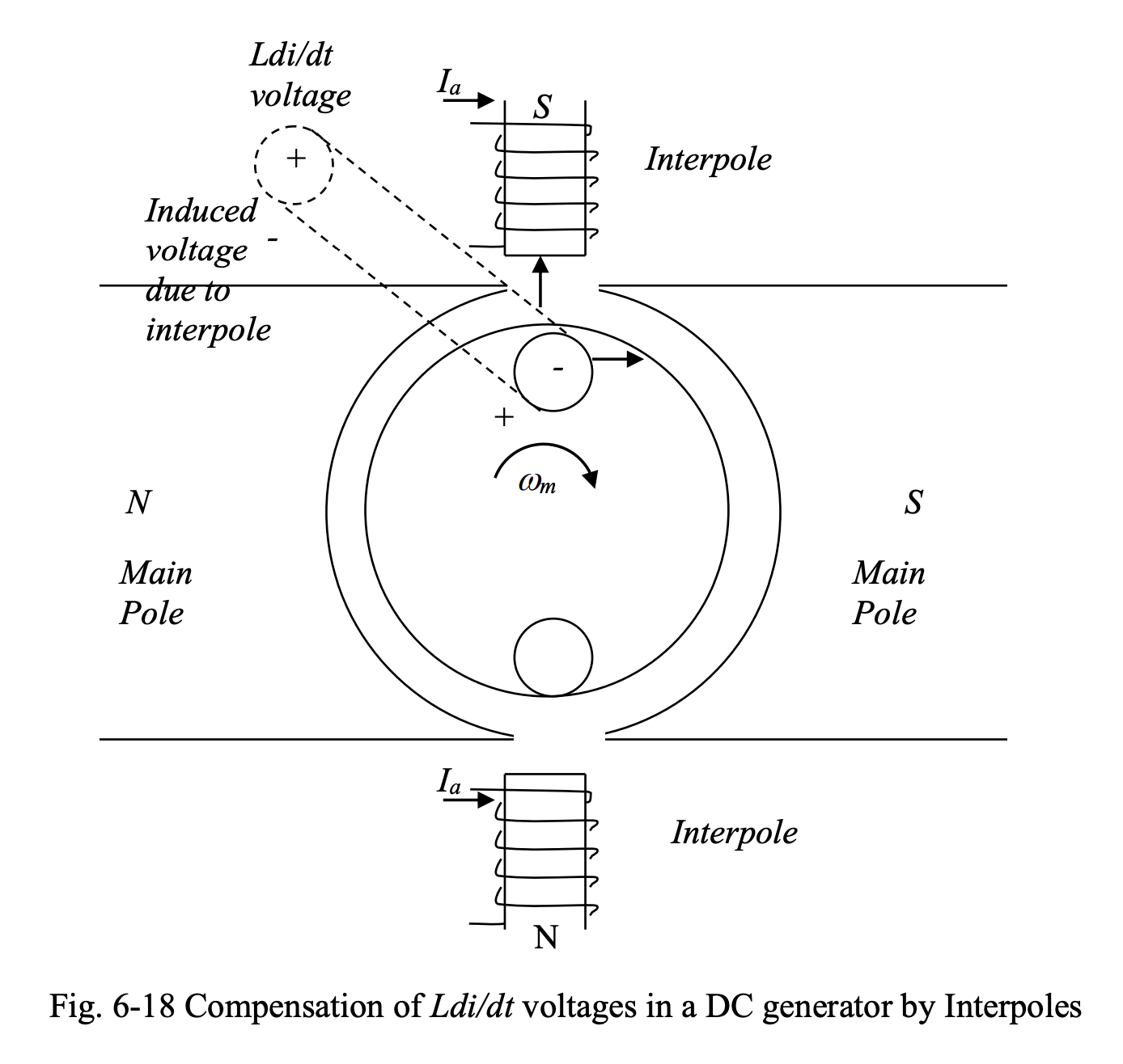
As the conductors pass by the interpoles, they cut the lines of the interpole flux, and as a result, a voltage will be induced in them. This induced voltage opposes the voltage and compensates for its adverse effects.The figure below shows the voltage and the induced voltage due to an interpole, in an armature conductor.
- For this to happen, the interpoles in a DC generator should have the polarity of the next main pole in the direction of rotation of the rotor.
- On the contrary, the interpoles in a DC motor should have the polarity of the previous main pole in the direction of rotation of the rotor.
In this course, the calculations related to compensating windings and interpoles are not covered. It is assumed that compensating windings and interpoles are present, and they successfully compensate for armature reaction and voltages produced in armature conductors in the process of commutation, to restore the desired operation of the DC machine