Below we have a schematic diagram of an electrical circuit composed of an AC voltage source, with an internal resistance, and a resistive load connected across the source terminals.
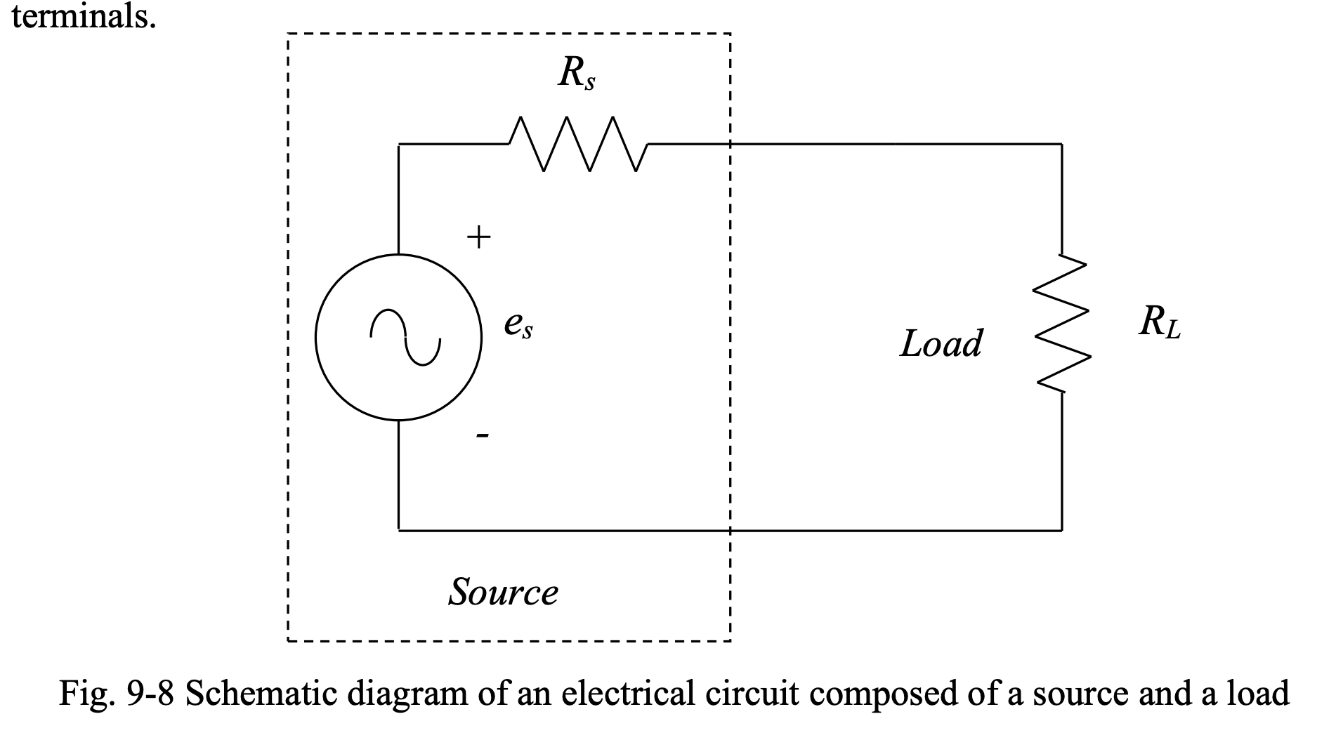
To maximize the power transferred from the source to the load, the condition must be satisfied. This is because:
Maximizing by solving gives us .
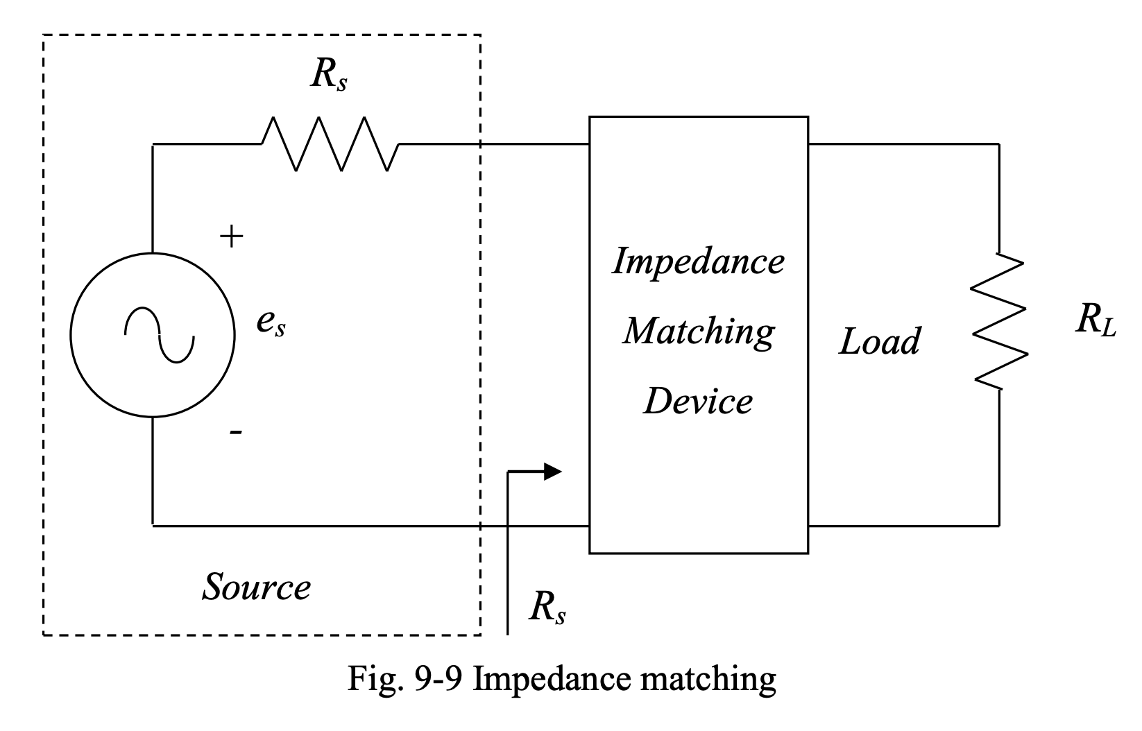
Since the load resistance is out of our control, we need to place a special device between the source and the load such that the resistance of the load, as seen from the source side, becomes equal to the source resistance. This is called impedance matching.
Transformers for Impedance Matching
Transformers can match the resistance of a load with that of the source:
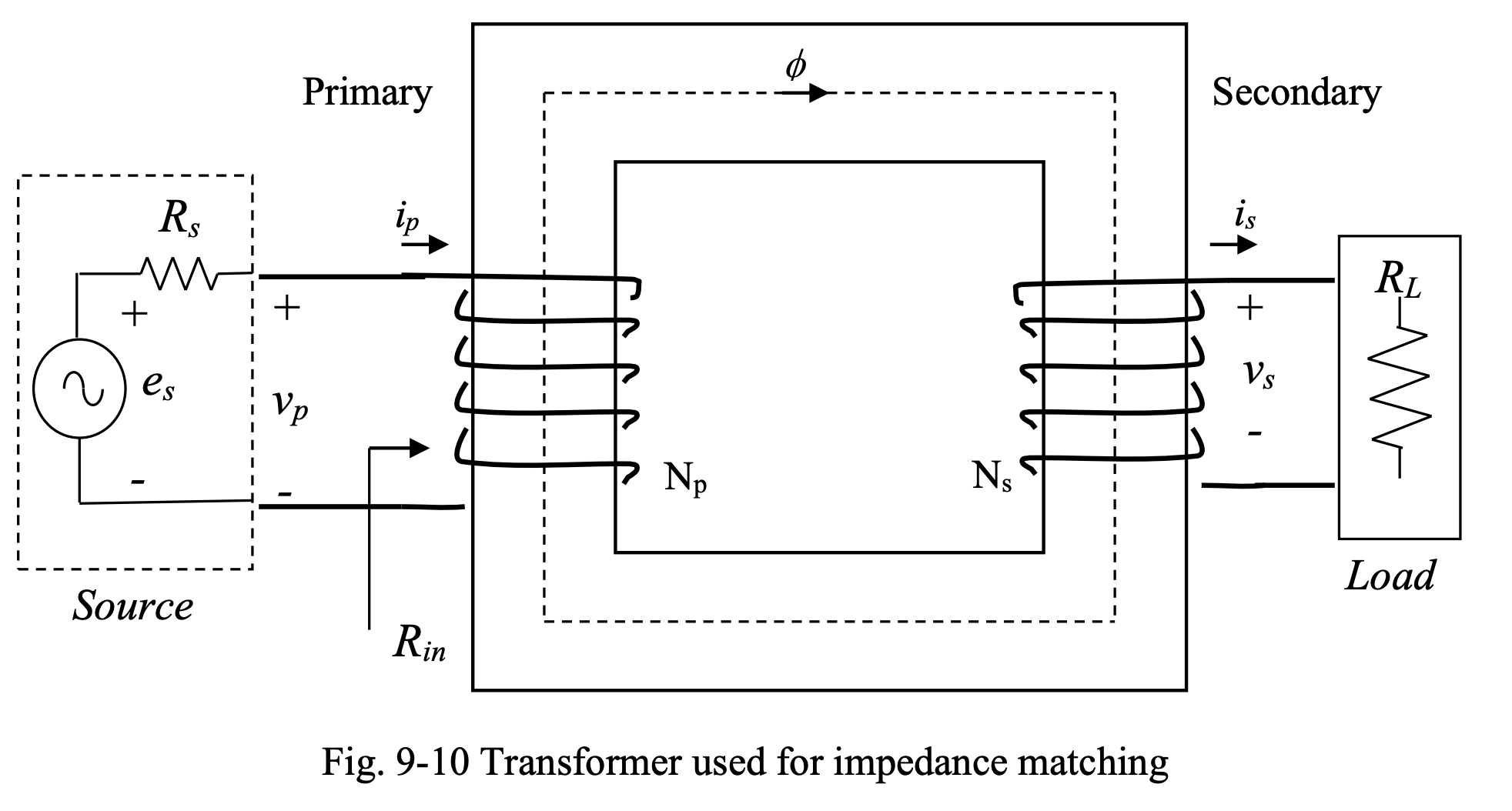
The idea is to design the transformer such that the resistance of the load, as seen from the primary side of the transformer, is equal to the source’s internal resistance. In other words, we want .
From the figure above, we can write:
Knowing that and , we can choose such that:
or: