Signal conventions for timing diagrams have variations based on whether the signal is a single or multiple wires (like if it’s a bus).
Single Wire Representations
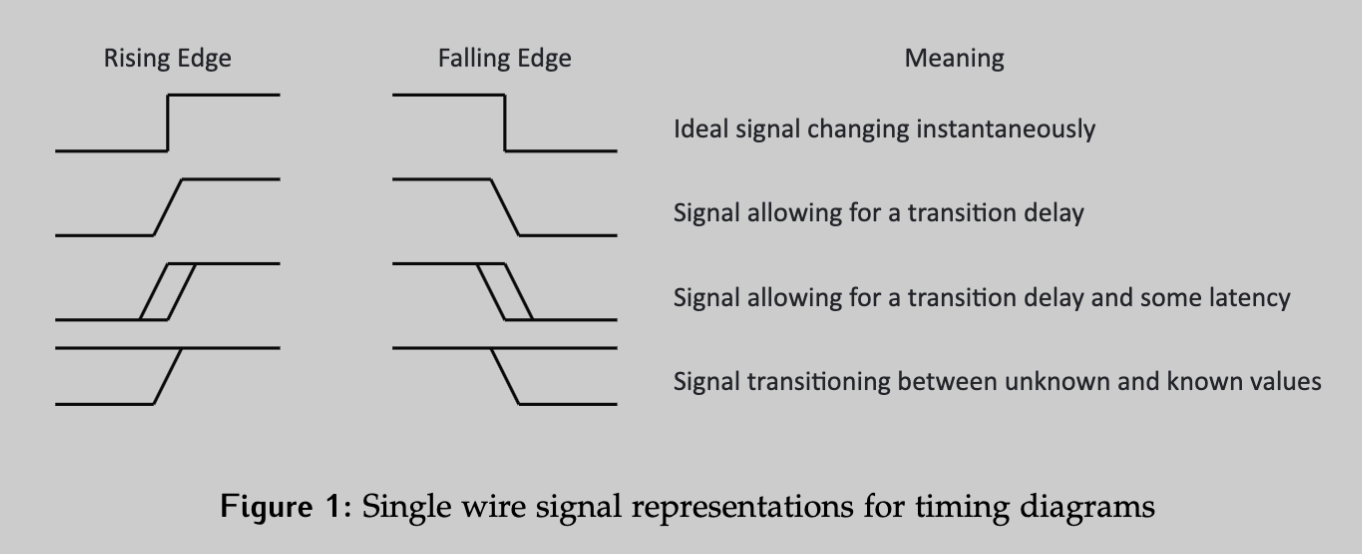
- An ideal signal would be able to change logic values instantly. If the time for the signal to change is significantly smaller than the time scale at large, drawing the change as instantaneous is a reasonable approximation.
- If the delay is significant with respect to the time scale, transition time can be accounted for.
- If there is latency or uncertainty in the timing of the change, a double edge can be used to show the bounds of the change.
- If the value of the signal is unknown or irrelevant before/after a period where the signal value does matter, we can indicate these “don’t care” values
Multi-wire Representations
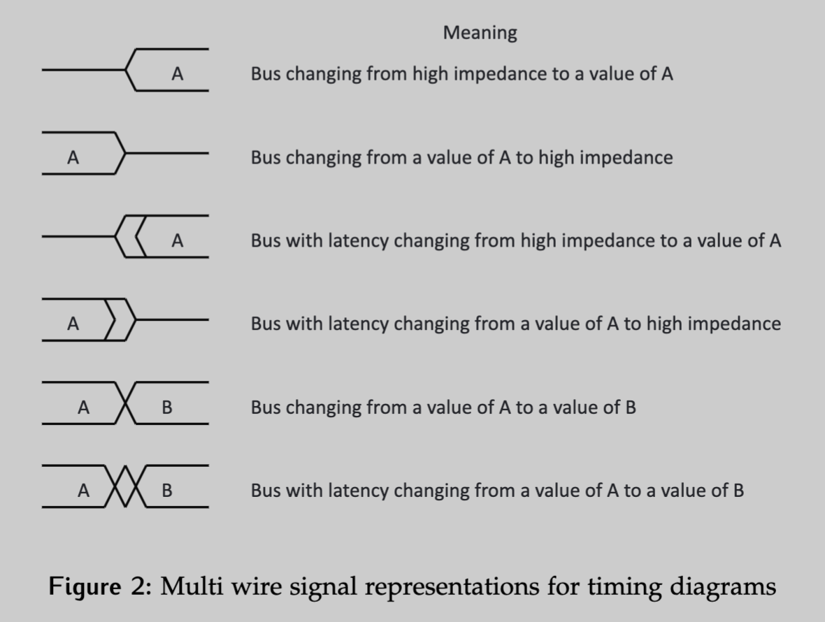
- A single line in the middle represents a line in a high impedance state, meaning it’s floating. It can also be used to represent a “don’t care” condition.
- When a known value is represented, line are drawn both at logic 1 and 0, and the current value is written between them.
- In the example shown, the value is written in hex as “A”.
- If there is uncertainty, or latency, in when the signal changes the bounds are indicated with double lines as shown in the 2nd and 3rd examples.
- When a bus line changes values, a cross is used.
- Not all signals in the bus will change at the same time; thus, bus changes are sometimes drawn with some uncertainty between the changing values, as shown in the final example.