Distributed arbitration systems have two component types:
- Central arbiter (CA): Responsible for monitoring requests and deciding when to issue permission for a device to take control of the bus.
- Distributed arbiter (DA): The distributed arbiter allows a device to make a request, and lets the device know when it has control of the bus.
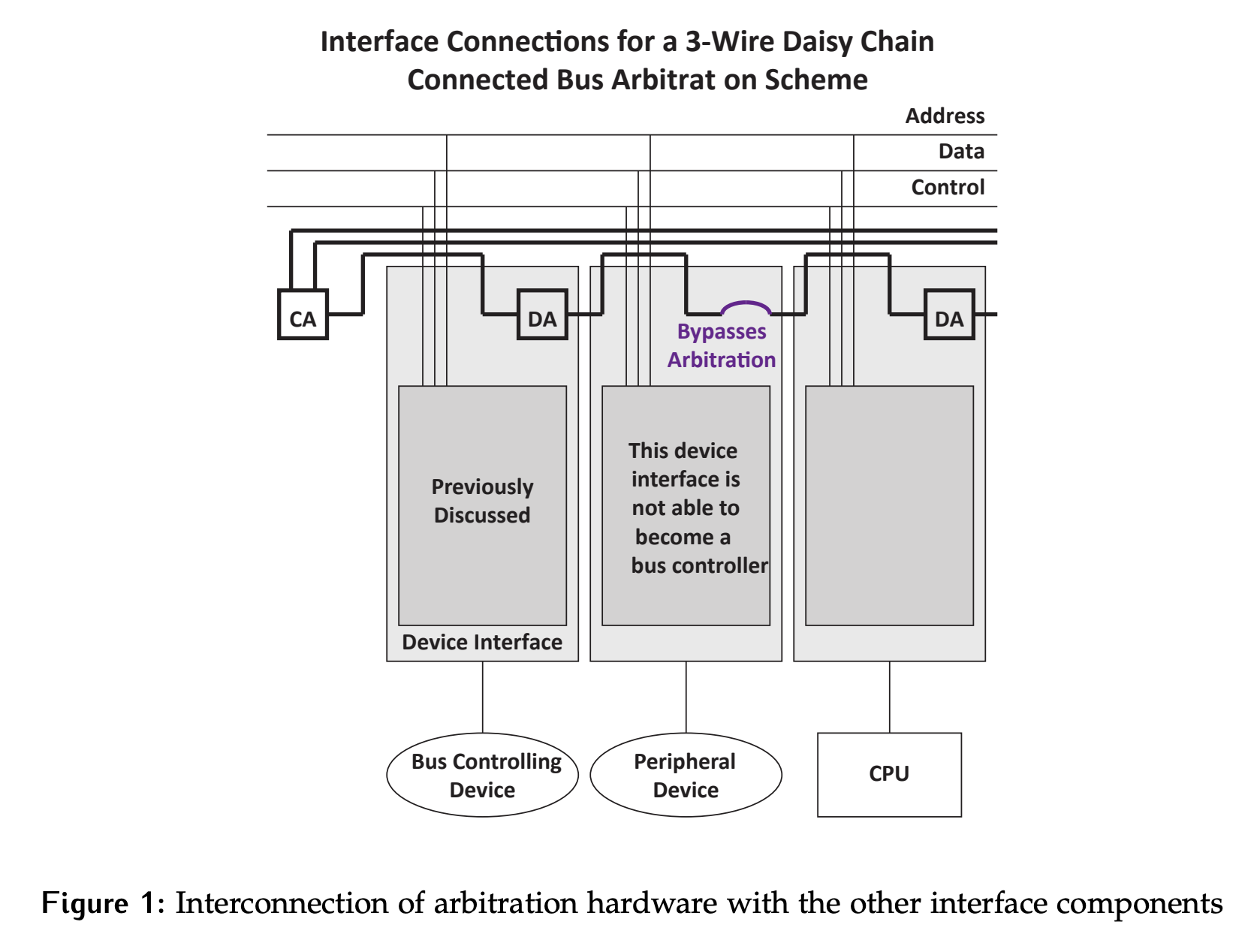
Consider the high level view shown below in Figure 1.
- Two additional shared wires are required in addition to the system bus lines per the model used in previous sections. These lines are inputs to the central arbiter and allow it to determine if anyone is making a request and whether the bus is currently in use.
- The CA has one output line that is used to indicate permission to use the bus. This permission signal is often called a token.
- Notice that in this case, the token gets passed from one device to the next through the DAs. This is where the “daisy chain” part of the name comes from. For devices that aren’t capable or aren’t configured to act as a controller, they can either pass the signal through as shown, or they could have no connection to the arbitration system in the first place.
3-Wire Daisy Chain
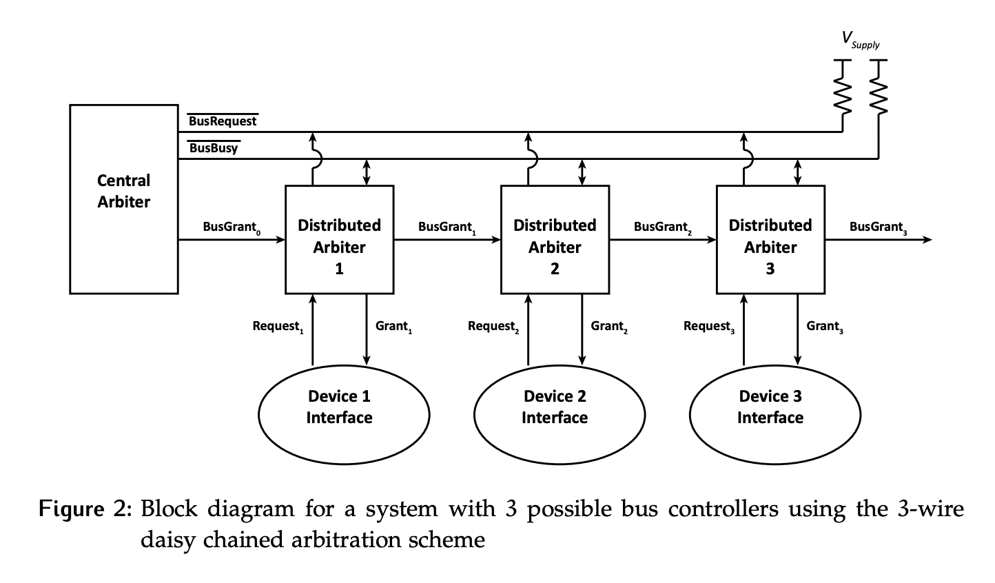
One specific distributed arbitration scheme is the 3-wire daisy chain. Consider Figure 2, where we have a system using the 3-wire scheme with one central arbiter and 3 devices, all of which are capable of being bus controller and therefore have distributed arbiters. The system uses two shared open-drain lines with pull-up resistors.
Operation
A device wishing to make a request will assert its local request line, which are called Request_x in the diagram. When the DA_x sees the request, it asserts /BusRequest to indicate a request to the CA. This is an active low line, as indicated by the name and the passive pull-up. /BusBusy is used to indicate if a device is currently using the bus. It is also active low. When the bus is available and there is a request, the central arbiter issues a token by asserting BusGrant_0. The rising edge on this signal is effectively the token for this system.
When it sees the token, DA_1 will look at whether or not Device_1 is making a request.
- If
Request_1 = 1, then device 1 is looking to use the bus and DA1 will assert its local grant signal, Grant1 to tell the device it has control of the bus. - Otherwise, the token will be passed to
DA_2by assertingBusGrant_1. This is the daisy chained part of the arbitration.
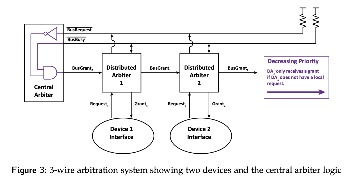
Notice that this results in a fixed priority relationship between the devices. The device closest to the arbiter gets the first opportunity to take the bus, so it has the highest priority. The device furthest from the CA will have lowest priority, as shown in Figure 3.
Numbering Convention: Each DA is numbered through , with being closest to the CA. Its local Request_x and Grant_x lines are subscripted with its number, as is its BusGrant_x output. The incoming BusGrant_x is i-1, with BusGrant_0 being the signal driven by the CA.
This system could theoretically support any number of devices, although the ones farthest from the CA may have difficulty getting control of the bus. Another device can be added by connecting BusGrant_3 and the two shared lines (/BusBusy and /BusRequest) to another DA.
CPU Placement
Where should the CPU be in the chain? While the CPU is an important part of the system, it also makes the most requests. If we have CPU as Device_1, we might starve other devices. Thus, CPU should actually be the lowest priority device. The system needs to make sure it doesn’t starve the CPU; this is done by imposing limits on how many bus cycles a device is allowed to hold the bus for.
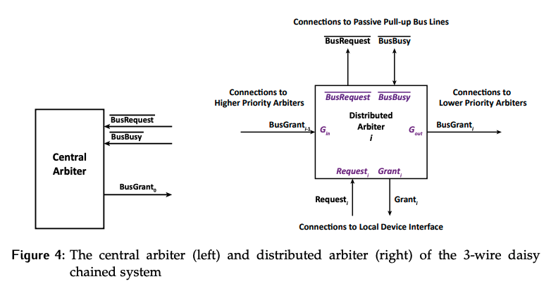
Central Arbiter
The central arbiter’s job is to control access to the bus, ensuring that only one has access to the system at any given time. It uses the /BusRequest and /BusBusy signals to decide when to issue a grant.
Under what conditions should BusGrant_0 be set? In other words, under what conditions should a token be issued? It should be asserted if the bus is not busy, which means /BusBusy = 1 and if there is a request, so /BusRequest = 0.
This means the central arbiter is just combinational logic with an AND and a NOT gate. Since the signals have to pass through this logic, there will be some small delay between when the inputs have the correct values and when the token is actually generated. This is called central arbiter delay, .
Distributed Arbiter
The logic inside the DA is far more complex than the CA. Instead of being purely combinational, they are now a function of both inputs and state; this will not be covered here. Instead, the focus is on how using the models shown above in Figure 4.
Anytime a signal needs to be processed by a DA to set an output, there will be delay. This delay is called distributed arbiter delay, and will not be 0.
- In reality, this delay varies based on the path through the internal logic; however, differentiating those paths and assigning different times gets very complicated, so we simplify the model by assigning a single delay time for work done by the arbiter.
- There is also a delay to assert a signal on the shared bus lines, which is called . However, this tends to be much shorter than or , and so it will be approximated as 0.
1-Device Request Timing
Consider a system with two devices shown in Figure 3. Some assumptions:
- The system is non-preemptive.
- A device cannot change its mind once it makes a request. This means that the request can only be cleared by the device getting control of the bus.
The ladder diagram of the signal timing for to request the bus when the bus is currently available is shown in Figure 5.
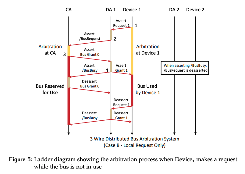
- When Device 1 needs the bus, it asserts the local request signal,
Request_1, to DA 1. - DA 1 responds by asserting
/BusRequestto the CA. - CA sees that
/BusRequestis s asserted while the bus is not currently in use, soBusGrant_0is asserted. - DA 1 sees the permission token
BusGrant_0(rising edge). SinceRequest_1is asserted, Device 1 is waiting to use the bus. DA 1 takes control by completing 3 actions:- Assert the local grant (
Grant_1) to tellDevice_1it has the bus. - Assert
/BusBusyto indicate the bus is in use. - De-assert
BusRequest_1since its now been filled.
- Assert the local grant (
- If Device 1 had not been requesting use of the bus, the token would have been passed on to the next device in the chain by asserting
/BusGrant_1. - At this point, arbitration for the bus has completed successfully, but there is some cleanup required. The assertion of
/BusBusywill cause the logic in CA to change from true to false, which will de-assertBusGrant_0. This deassertion will be propagated down the chain of DAs until it reaches the device with control of the bus, at which point the token has been cleared. - When Device 1 is done using the bus, it will deassert
Request_1to let DA 1 know. - DA 1 will deassert
/BusBusyto indicate to the arbitration system that the bus is no longer in use and deassertGrant_1to indicate toDevice_1that it is no longer in control of the bus.
The arbitration time depends on whose perspective we are considering. From the CA’s perspective, it took only . From Device 1’s perspective, it took the time it asserted Request_1 until it received Grant_1.
Multi-Device Request Timing
Arbitration is more interesting when there is more than one device looking to use the bus. Figure 6 presents the timing diagram perspective of the arbitration cycle between two devices wanting to use the bus. To see which devices are involved, check the Request_x signals. From these signals, Device 1 made a request, then at a later time Device 2 made a request.
Without looking at any of the other signals, it is possible to determine that Device 1 got control of the bus first, and later Device 2 was able to use it. How? By looking at when the Request_x signals were deasserted. Remember the restrictions for this system: it’s non-preemptive and a request is only cleared once the device gets use of the bus. This is a trick you can use to check your work when completing timing diagrams. You already know from the Request_x signals which device should get the bus, so if this is not what your arbitration shows you know something is wrong.
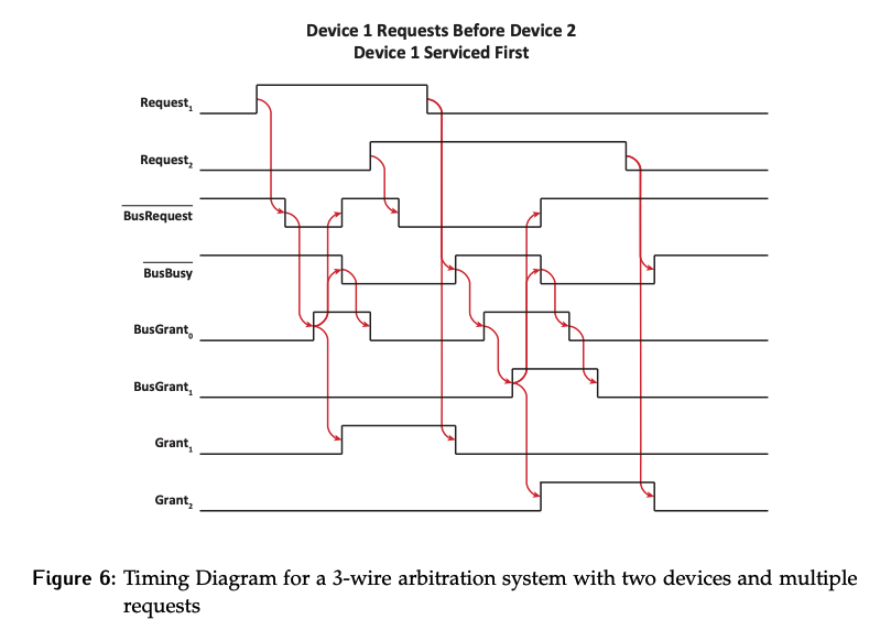
While time has not been explicitly marked in this diagram, there is a delay between an input to either the CA or a DA and the output signals that are generated as a result. In this diagram both and have been assumed as one time unit. There is a dependency between the signals which can be followed through the arbitration cycle.
- Device 1 makes a request by asserting
Request_1to DA 1. - DA1 sees
Request_1asserts/BusRequest. - Since the bus is not in use, and there is a request, the CA asserts
BusGrant_0. - DA 1 sees that the permission token
BusGrant_0is asserted and must now do 3 things:- Assert
/BusBusyto indicate the bus is in use. - Deassert
/BusRequestsince the request has been filled. - Tell Device 1 it has use of the bus by asserting
Grant_1.
- Assert
- While Device 1 is using the bus, Device 2 makes a request by asserting
Request_2. - Since the bus is in use, nothing more can happen until Device 1 is done using the bus.
- Device 1 indicates that it is done with the bus deasserting
Request_1to DA 1. - DA 1 sees that Device 1 is done and does two things:
- Deassert
Grant_1so thatDevice_1knows it no longer controls the bus. - Deassert
/BusBusyto indicate to the arbitration system the bus is available.
- Deassert
- Now that the bus is still available and a request is being made, the CA will once again
BusGrant_0. - DA 1 sees the token and that
Request_1is not asserted at this time. Thus, the token is passed on by assertingBusGrant_1. - DA 2 now sees the incoming token. It will perform the same 3 actions as
DA_1did in step 4. - From this point on, the process is the same as it was for the previous cases that have been considered, except now it is Device 2 and DA 2 interacting with the system.
Timing From Device Perspectives
The same example is shown in Figure 7 with no markup to indicate where arbitration and usage are taking place from the perspective of various devices.
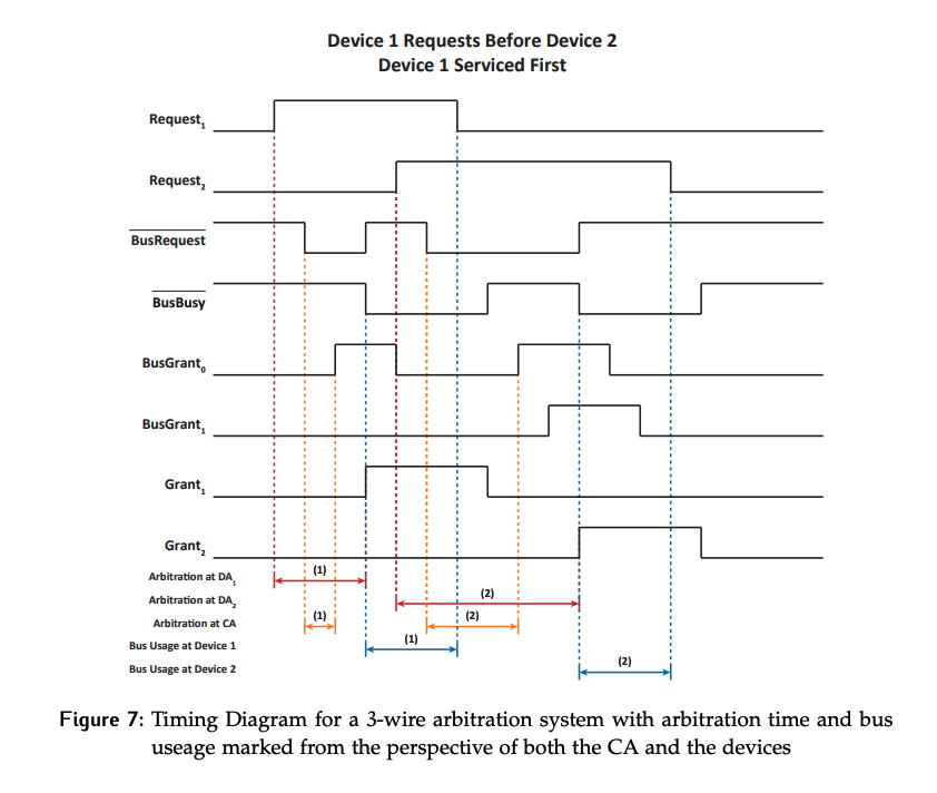
- From DA 1’s perspective, arbitration lasted from the time of the local request until it issued the local grant.
- From the central arbiters perspective this time was much shorter, just from when it saw
/BusRequestto when it issuedBusGrant_0.
For the second arbitration cycle from DA 2’s perspective, arbitration started when the request was made, and again ended when the local grant was issued, but the cycle is considerably longer than arbitration was for Device 1. There are two reasons for this:
- Device 1 was still using the bus this request was made.
- The grant had to propagate farther from the chain.
This arbitration cycle also took longer from the CAs perspective, again because the bus was in use at the time of the request, so the grant could not be immediately issued. The CA had to wait for /BusBusy to be deasserted. The time where a local grant signal is high marks bus usage from the device’s perspective.
Consider another arbitration cycle example as shown in Figure 8. In this case, the bus is initially idle since /BusBusy is not asserted. Looking at the request lines, only Device 2 ever makes a request and it gets control of the bus. The process of arbitrating for the bus will be the same as before.
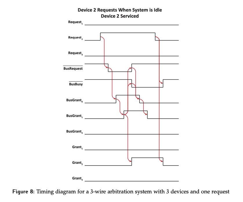
Of particular interest in this example is how BusGrant_x gets propagated for assertion and deassertion.
- The fact that
/BusBusyhas been asserted will be enough to causeBusGrant_0to be deasserted. - When DA 1 sees that the grant it passed on has now been taken away, it will pass this on by deasserting
Grant_1. If the device using the bus was further down the chain, this passing would have continued until allBusGrant_xlines were 0. - Nothing more can happen now until Device 2 finishes with the bus, at which point it will deassert
Request_2, which will cause DA2 to deassert/BusBusyandGrant_2.