Regardless of the type of DMA controller implemented, there is some configuration that needs to be done.
Like other peripheral interfaces, there is some setup work required to enable the DMA controller and configure it and the device appropriately for it to function. We also need to enable and configure interrupts if we want to use them. This work that is done once is part of the global initialization. Once the main loop of the program is entered, the CPU may interact with the device like any other peripheral using single cycle read and write operations.
At some point, the CPU will want to use the DMA controller for a block transfer. This will require block initialization, which is done once per block to setup the device or device interface. The CPU writes control values into the DMA controller registers such as the byte count in the BCR, starting address in the MAR, and control information such as interrupt enable/disable.
There is also work that must be done once for every transfer:
- Device – Some event causes the device to have data or to be ready for data. This could be indicated by setting a status bit.
- Device Interface – Requests a transfer from the DMA Controller.
- DMAC – Requests/receives control of the bus through the bus arbitration system.
- One or more of the following cycles occurs. The actual number depends on the transfer mode:
- DMAC – Causes either memory data to be written to an interface (read), or an interface’s data to be written to the memory (write)
- DMAC – Decrements
BCRand incrementsMAR
- DMAC – Releases the bus
Once all bytes in the block are transferred, block synchronization will occur. The DMAC tests the BCR; if it is now zero, the DMAC sets the DMAC status bit, or interrupts the CPU if DMA interrupts are enabled. Although the test is performed for each DMA transfer, the action of informing the CPU is only performed once per block when the BCR has a value of 0.
The DMA controller will complete the transfer, and once it is complete, the CPU can interact with the device as a peripheral or configure another block for transfer in the DMAC.
Transfer Diagrams
DMA Block Transfer
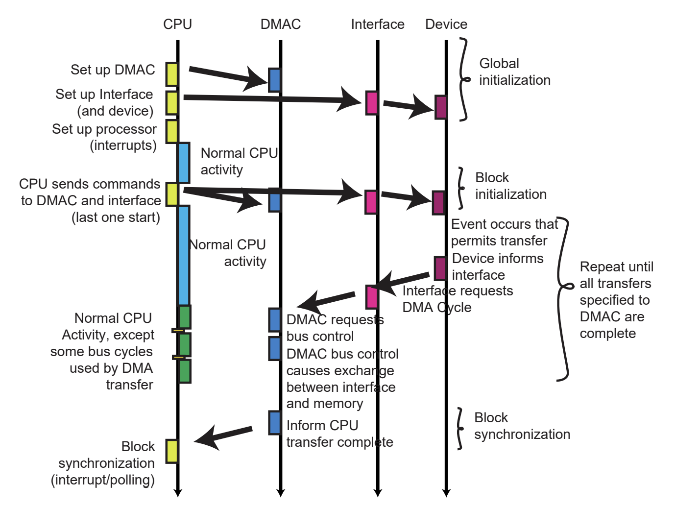
Figure 10 below shows global initialization followed by a block transfer. After the block is complete, some cleanup may be required. Note that activity to the left of the ladder rung is associated with the block transfer, while any activity shown to the right is other unrelated work that can be completed.
Tight Polling
For comparison, Figure 11 shows the same block of data being transferred using tight polling.
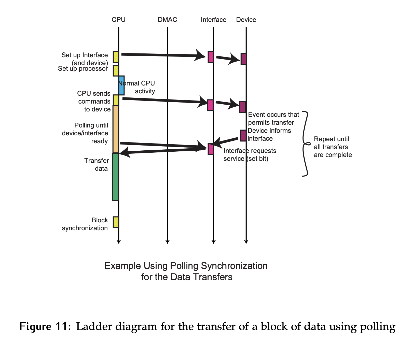
- Global initialization will be run once at the start of the program.
- At some future point in time, a block transfer will be initialized. There may be some initial work done to configure the amount of data in the block, the starting address, etc.
- For every unit of data to be read, the CPU will poll the interface until a unit of data is available. When it sees that one is, the transfer will be done.
- This process will repeat until the entire block is read. Notice that while the block transfer is happening, there is no opportunity for the CPU to accomplish any other work.
- At the end of the block, some cleanup may still be required by the CPU.
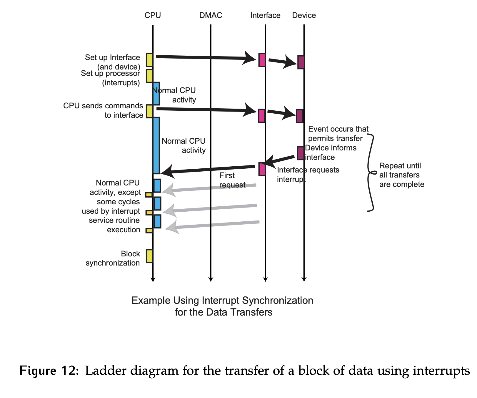
Interrupts
For the same transfer using interrupts, the global initialization will also include configuring the interrupts. In terms of the block transfer itself, the primary difference is the ability for the CPU to accomplish other work while data is being produced. Notice there are periods of normal activity (shown to the right of the CPU rung) interspersed with short periods of data transfer as shown in Figure 12. As before, some cleanup may be required once the entire block has been transferred.