Armature reaction is a phenomenon caused by the interaction of magnetic fields of the stator and rotor (i.e., field and armature windings) in DC machines. Armature reaction has an adverse effect on the success of the commutation process.
The figure below shows the stator and rotor of a simple, 2-pole/1-coil DC machine with no current passing through the winding, .
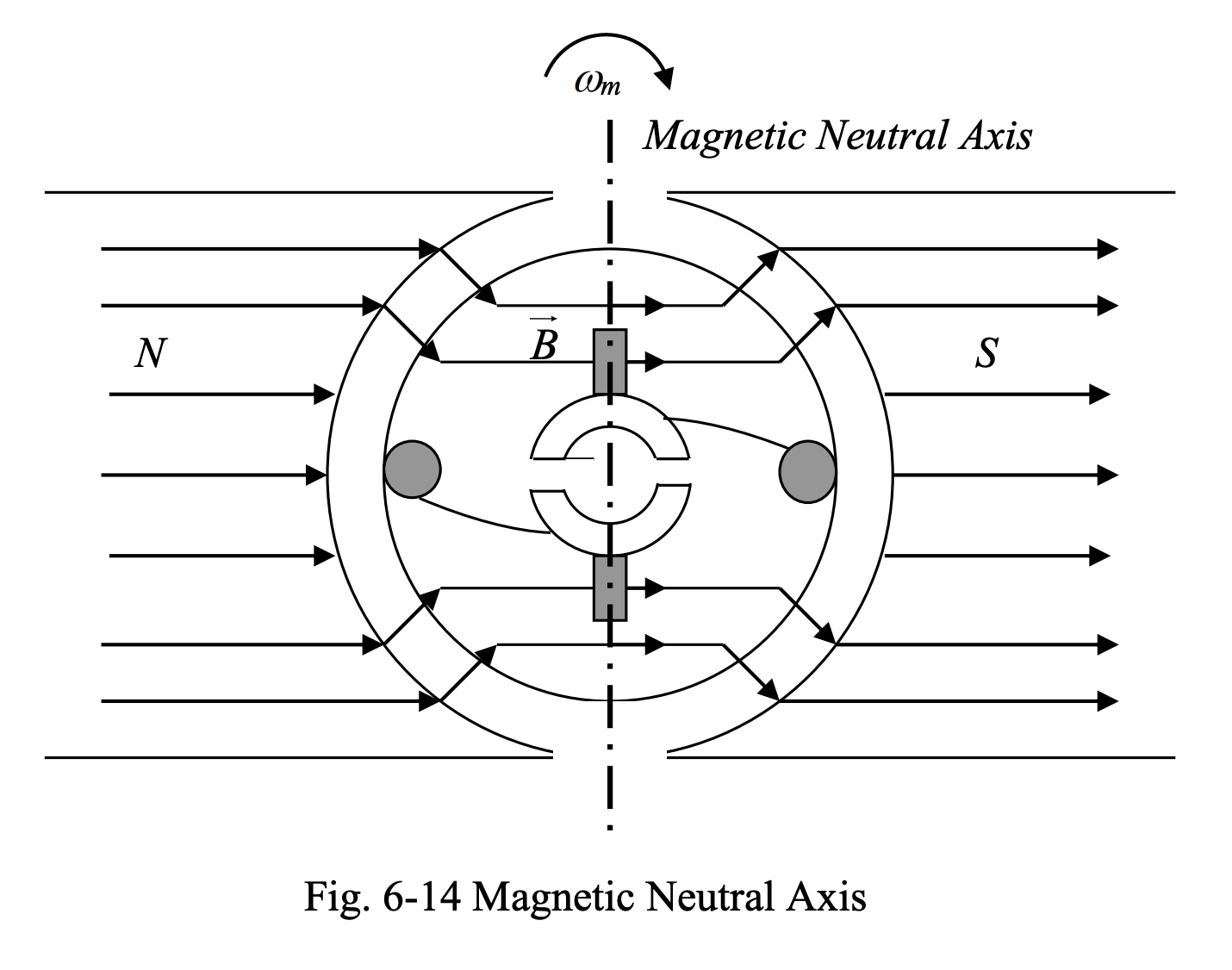
- When the rotor rotates through with respect to the position shown, such that the linear speed of the loop sides are in parallel with magnetic field, no voltage will be induced in the loop sides, since .
- This is the moment at which commutation takes place; the brushes short circuit the commutator segments momentarily and move from one segment to another. Zero induced voltage will ensure no sparks will be produced at the time of switch-over.
- The axis defined by the position of the loop sides, when induced voltage in them is equal to zero, is called the magnetic neutral axis. This axis corresponds to the correct position of the brushes and is perpendicular to , as shown.
When current is passing through the armature conductors, the situation is different. Below we have for the two cases of generator and motor.
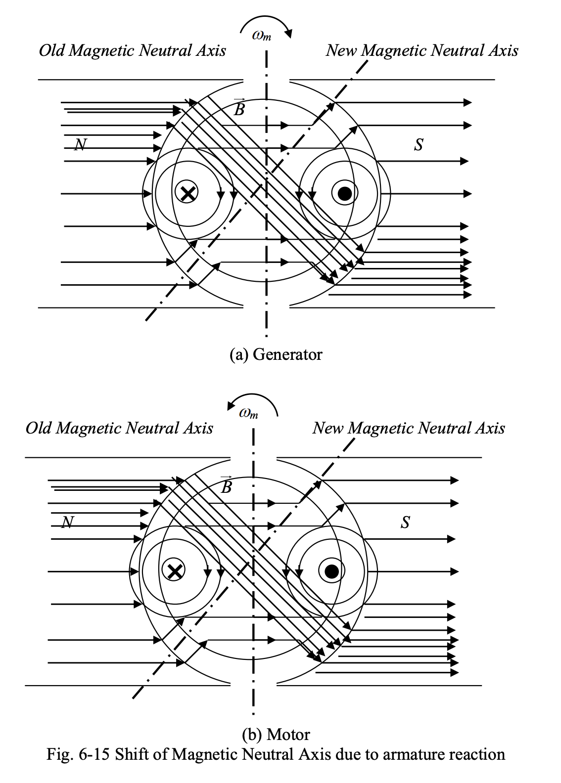
Due to the armature current, a magnetic field will be set up that tends to weaken the magnetic field of stator in some areas, and strengthen the stator magnetic field in other areas. This will alter the pattern of lines of flux in the machine and shift the magnetic neutral axis.
- The extent of shift in the magnetic neutral axis depends on the magnitude of the armature current.
- When the magnetic neutral axis is shifted with respect to the default position, which corresponds to the position of the brushes, the switch-over between the commutator segments takes place at a moment of time, when the induced voltages in the loop sides are not zero. This causes the ignition of sparks between the brushes and commutator segments, which gets more severe as the armature current increases. Sparking accelerates the wearing of commutator segments and brushes due to local heating.
One way to get around this problem is to change the position of brushes according to the shift in the neutral axis. In generator mode, the brushes must be moved in the direction of rotation of the rotor, whereas in motor mode, the brushes must be moved opposite to the direction of rotation of rotor.
- However, the angle through which the brushes must be rotated, to correspond to the new position of neutral axis, is not exactly known at any moment of time. Modifying the position of brushes to correspond to the new position of neutral axis will be successful only in the case of constant armature current (constant electrical load in generator mode or constant mechanical load in motor mode).
- This approach is obviously not practical for varying armature current. A better solution will be one that compensates for the effect of armature reaction automatically and irrespective of the magnitude of armature current.
A dynamic solution to the problem of armature reaction is to use additional compensating windings, in the stator. These windings carry the armature current and are arranged in such a way that their magnetic field opposes the rotor magnetic field at pole tips. This has been illustrated below.
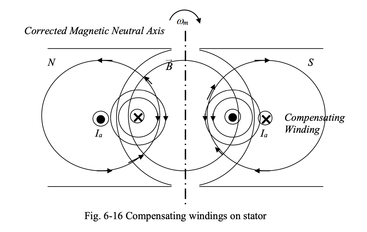
As seen above, the magnetic field produced by compensating windings nullifies the effect of armature reaction, which is diverting the lines of flux and shifting the magnetic neutral axis. The correction of the position of neutral axis is based on the instantaneous magnitude of armature current. As a result, this method works successfully under all loading conditions.