Interrupt Function Loading
Interrupts happen at random. Usually, when code calls a function, it does so in a deterministic way – it is always clear that the next instruction will be a function call. Therefore, when the code gets written into an executable, the compiler knows exactly where to put the function call instruction, and knows exactly which function it needs to call. This is not so when an interrupt occurs.
Most modern CPUs have a type of array that stores interrupt function pointers. This array in the Cortex M series is known as the vector table.
There are several named interrupts (Hard fault, SVCall etc.) and several seemingly generic ones (IRQ*). It is the programmer’s responsibility to fill in this table, but most IDEs you’re going to use does this for you. This table stores function pointers, and the actual setup looks like:
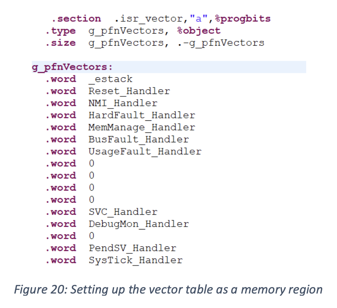
In this code, which has to be written in assembly because it runs so early that stacks aren’t set up yet, all that is happening is we are telling the assembler that there will be functions with the given names stored in memory.
The setup code for the IDE then provides template functions that generally do nothing – it’s up to the programmer to actually implement them.
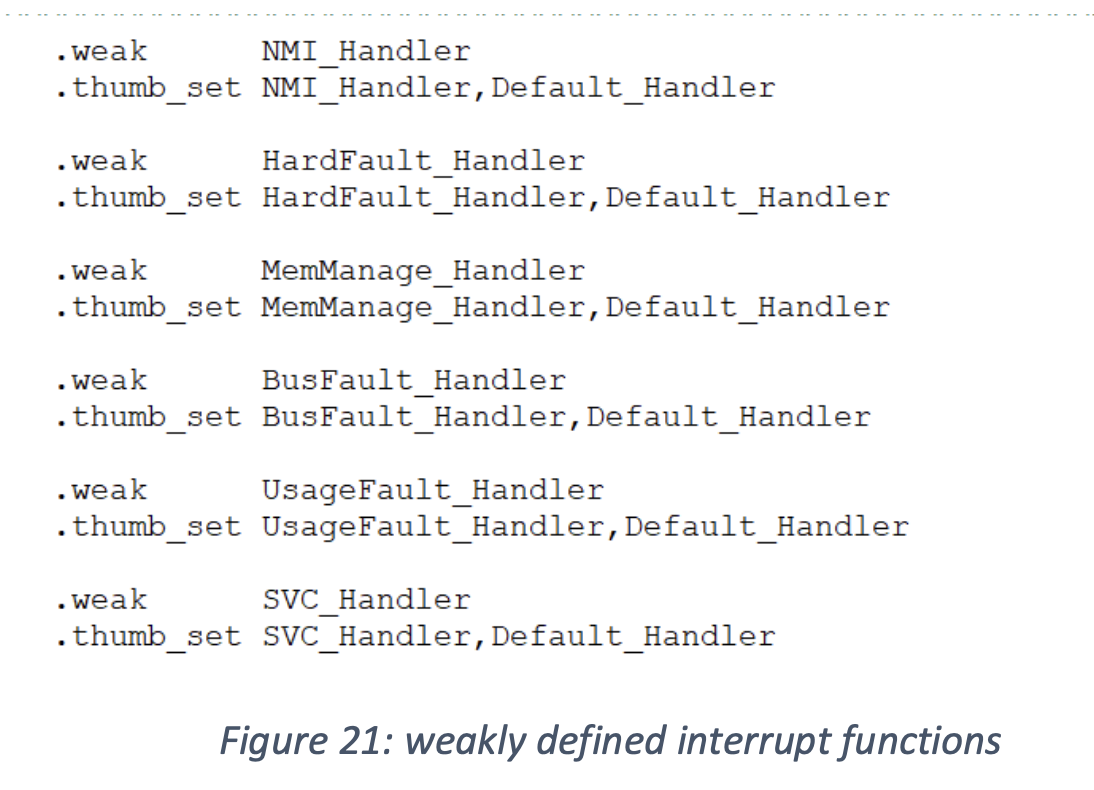
The “.weak” keyword indicates to the linker that if another function with the same name is encountered, use that one.
Why not just leave the vector table uninitialized? Well, for some interrupts that’s fine – an interrupt that we never anticipate will occur doesn’t need any code dedicated to it. However, the various fault handlers have to be created because they occur precisely when our code does something wrong. Since we can’t be sure we are writing bug-free code, we need to have something for the chip to do if it encounters a fault. In this default code all that happens is that the function gets called, and later it is defined to be a simple infinite loop. By doing this, we ensure that a fault condition doesn’t get worse by trying to run code that itself is just garbage.
Interrupt Selection
There is a subcircuit on the CPU, called the Nested Vectored Interrupt Controller (NVIC), that keeps track of which interrupt is triggered. This is just a set of bits mapped to each location in the vector table, and there are four states an interrupt can be in:
- Pending: the interrupt has been triggered, but the chip hasn’t serviced it yet. This state is used to force the chip into the interrupt mode.
- Active: the interrupt is running but not yet complete.
- Pending an active: this happens when the interrupt is still running, but the conditions for it have happened again.
- Inactive: the interrupt is neither pending nor active.
The NVIC is constantly checking its bit fields. Once an interrupt is pending, it triggers the interrupt mode. When an interrupt goes inactive, it handles the return from the interrupt.
Nesting and Priority
What happens if an interrupt occurs while the CPU is already servicing an interrupt?
There are a few options, and they all depend on priority. Interrupts are given priority levels. There are some interrupts, like hard faults, that must take priority over most others because they indicate that the chip has been given bad instructions.
In the ARM Cortex series, interrupt priorities are such that lower numbers indicate higher priority. Some priorities are configurable, while others are set by the manufacturer. Here is an example from the Cortex M3/M4, of interrupt priorities:
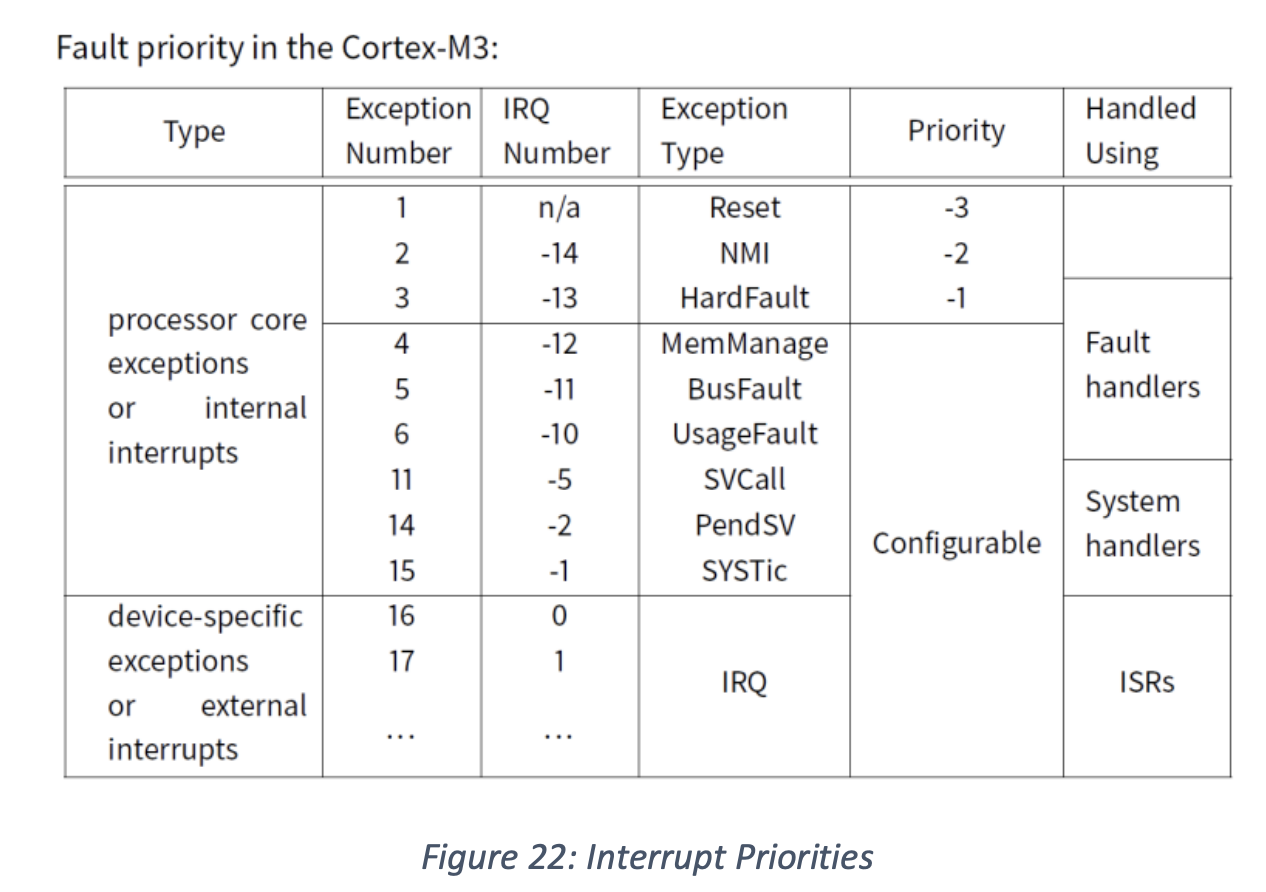
The important ones, like reset or hard fault, are at the very top. Others, especially ones that are device-specific, are configurable but can never be set higher than the fixed priority interrupts.
Priority Cases
Let’s assume we are servicing an interrupt with a priority level and a new interrupt comes along:
- Case 1 – new interrupt has higher priority: In this case, the new interrupt should take priority and interrupt the already running one. Since the registers are all saved already, the new interrupt does not re-save them. The original interrupt stops, the new one is serviced, and we return to the stopped interrupt before returning to the main code. This is known as “nesting”, in that one interrupt is nested inside of another.
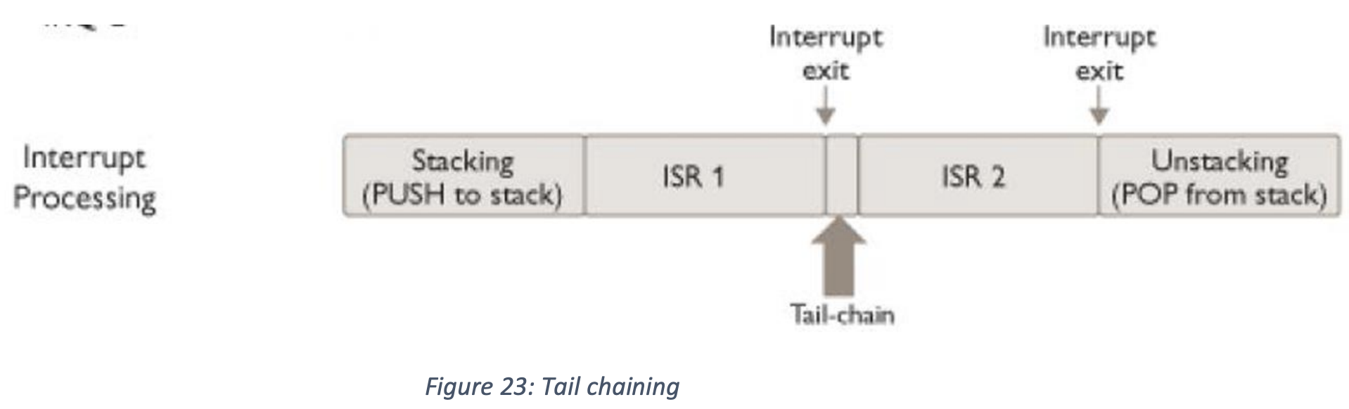
- Case 2 – new interrupt has lower priority: In this case, the new interrupt is pending but not yet serviced. The chip undertakes what is known as “tail-chaining”: the registers are once again not pushed, since they’ve already been pushed thanks to the first interrupt, but in this case the first interrupt does not get interrupted. It completes and then the next interrupt continues. This looks like this:
- Case 3 – new interrupt as the same priority: this case is the same as case 2.