In the early 1990’s, if we wanted to connect a new device, such as a joystick to play a new game, we’d have to turn off the computer, open it up, install a card with the proper connector, close the computer back up, connect the joystick, and power the whole thing back on.
A group of companies set out to design a protocol that would be plug-and-play, resulting in the USB standard. The first iteration was not widely adopted but USB 1.1 became widely included in personal computers, popularized by the Apple iMac.
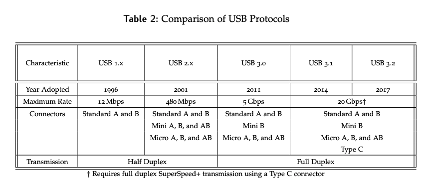
While the USB was successful in meeting some of its goals, others were only partially met; for example, there was never a single connector, as both the A and B connector variations have existed from the beginning. Now we have even more, with mini, micro, and USB C. A major goal that USB did meet was the ability to support for power distribution.
USB 2.0 came in 2001 and significantly increased data rates, making it possible to stream video and audio over USB, making devices like external webcams cheap and ubiquitous. This was the gold standard in serial communication until USB 3.0 was released in 2010 and entered the mainstream market in 2011. It added more pins inside the connector, providing a full-duplex channel, and increased data rates to 5 Gbps.
A key feature of USB is backwards compatibility. You can plug an older device into a 3.0 port and it works, and USB 3.0 devices can operate on older ports, albeit at speeds limited to those of the lower protocol. USB 3.1 and 3.2 have further increased speeds to 20 Gbps. However, achieving these speeds requires USB-C connectors, which broke the backwards compatibility aspects previously seen with USB devices.
USB 3.1 / USB-C
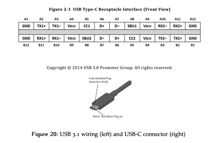
The wiring of the USB 3.1 protocol and a USB-C used with it are shown below in Figure 20.
- The USB-C connector is able to achieve such high data rates through the addition of two additional data lianes (TX AND RX), which were not present in 3.0.
- Furthermore, with USB-C, direction doesn’t matter; if we rotate it 180 degrees, we have the same pins in the same locations, although the subscripts change. The protocol has a mechanism to determine which way it’s been connected.
Expansibility
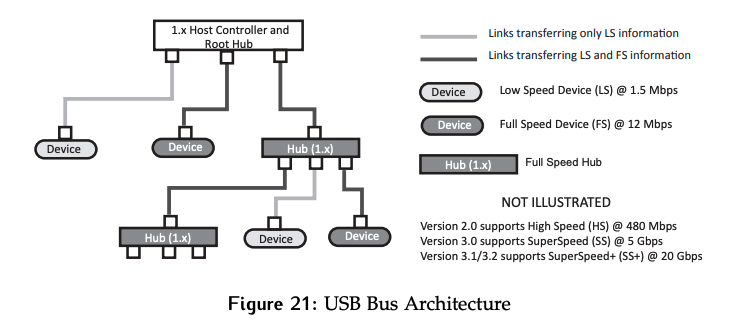
One of the goals of USB was to provide an expandable solution. USB provides this using a tree structure shown in Figure 21.
Inside your computer is the root hub, which acts as the controller and controls all transactions on the bus. Devices can then be connected, as well as hubs, which provide additional connections. For any given path back to the node, the speed will be limited by the slowest device along it. While the diagram is only drawn from the perspective of 1.x devices, which were capable of operating at one of two speeds depending on their needs, the hierarchical idea applies to the later standards as well.
Hardware Implementation
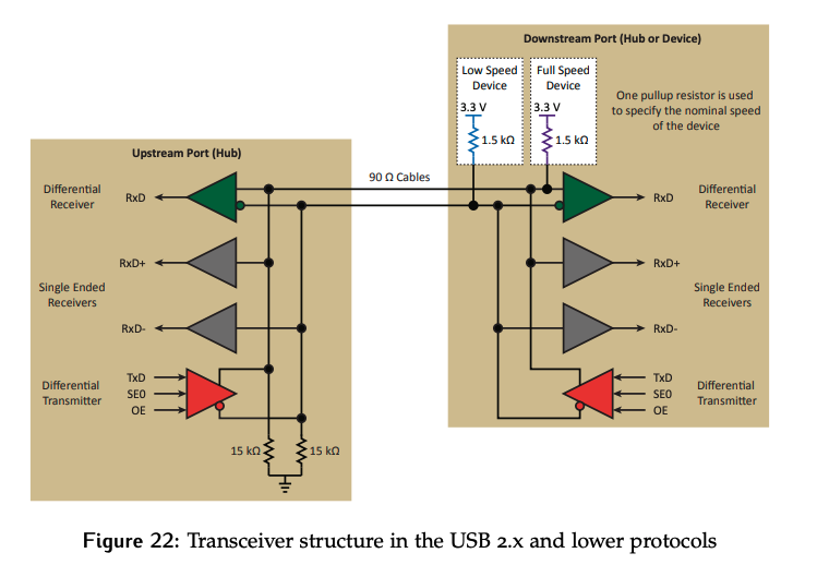
For USB 2.0 and below, there are four wires in the connector: power, ground, D+, and D-. The data lines are differential and implement a half duplex channel, as shown in Figure 22.
Hub Side
Look at the hardware on the hub side, shown on the left side above.
- USB uses differential signals for the data lines. This means two lines are used, one which carries the data value and one which carries the inverse of the data value at the same time.
- These lines are often twisted together for the protection against electromagnetic (EMI) it provides.
- A differential receiver is required to convert the signals back to the single-ended on/off encoded format the rest of the computer runs on.
The hub also needs to be able to drive differential signals, which is done using the differential transmitter. The transmitter has three input:
- Data
- Output Enable (
OE). This controls whether the data signal is being driven on the data lines or not, which is necessary since the data channel is half-duplex. - Single Ended Zero (
SE0). This signals sends a special out of band control pattern on the data lines by pulling them both to 0, something that should normally impossible for a differential signal. Since this should never happen on a differential signal, the differential receiver can’t interpret or detect it. These receivers allow the values on each of the data lines to be read directly.
Finally, the root hub has two pull-down resistors. They are used to passively pull the lines to 0 when they are not being driven so that they don’t float.
Device Side
On the other end, each device will have the same set of transmitters and receivers as the hub. In USB 1.x, they also had an additional resistor.
This extra resistor was used to tell the root hub whether it was a 1.5 Mbps low speed device, or a 12 Mbps full speed device.
- A resistor on the D+ line indicates full speed.
- A resistor on the D- line indicates low speed.
- Note that these resistors are only 1/10 of the value of the pull-downs in the hub; they are not capable of pulling the data up to 1. Instead they just elevate levels on the lines enough for the hub to detect.
- The root hub it can determine the speed at which it should communicate with the device without any information being exchanged, allowing for bit rate synchronization to be achieved.
Protocol
Data is transmitted on the differential using what the standard calls “NRZI” encoding; we called this encoding “differential”. 0’s are represented by a transition, while a 1 is signaled with no transition on the line. Bit phase synchronization is achieved by looking for the transitions corresponding to 0s.
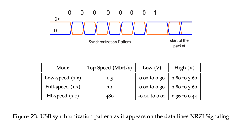
Like the asynchronous serial protocol seen previously, errors will compound over time. The signal integrity can only be preserved for so long before there will be sufficient error and the potential to mis-sample a bit. To ensure this never happens, bit stuffing is used; anytime there are six consecutive 1’s, a 0 will be inserted to allow the clock phase to be re-synchronized, and the extra 0 will be discarded by the receiver.
Byte synchronization is achieved using a specific bit pattern that is transmitted repeatedly anytime the line goes idle, and is required to sent before each packet.
- For USB, the special pattern is
0x01, or 7 zeros giving lots of edges for phase synchronization, followed by a1to mark the byte boundary. - Since this pattern must also be transmitted before every packet, it also plays a role in block synchronization.
- To mark the end of a packet, both data lines are pulled to 0 for two bit times. In other words, two single-ended zeros are sent.
Why do we use the word “packet” and not “frame”?
- The USB standard refers to them as such.
- Frame has a different meaning in USB. USB transmissions are split into 1 ms time windows called frames. Each one starts with a special “start of frame” (SOF) marker being sent by the root hub. During each frame, each endpoint is only allowed to be involved in one transaction, ensuring that all devices get serviced in a timely manner.
Packet Types
USB communication is asymmetric, meaning its controlled by the root hub. Devices can only respond to requests but cannot initiate them. As a result, each transaction is usually composed of a series of 3 packets:
- The USB token packet selects the device the root wants to interact with, as well as the specific register within the device being targeted. In USB, these are referred to as endpoints.
- Finally, this packet specifies the direction of the transfer, IN or OUT as seen from the root hub’s perspective. Like the parallel bus model, this packet plays the same role as the controller phase during a system bus transaction.
The USB data packet will be sent next, and contains the information to be transferred. If the direction for the transaction was IN, the device will be the source of this packet. If the direction was OUT, the root will send it. Full speed transfers in the early USB protocols could only send up to 64 bytes in a packet. Later versions of the same standard added isochronous data packets, which can transfer up to 1023 bytes at a time.
The USB handshake packet is not required for all transaction types. When used, it can be an ACK, acknowledging that all is well, and NACK, a negative acknowledgement indicating an issue or “no”. The sender of this packet will depend on the direction of the transaction.
Packet Format
The format of each packet needs to be considered as well. The packet will always start with the synchronization byte of seven zeros and a 1. It is then followed by a one byte packet ID, which indicates the packet type. The 3 different packet types needed for a transaction were discussed previously, and there are various options within each of them, which have different IDs.
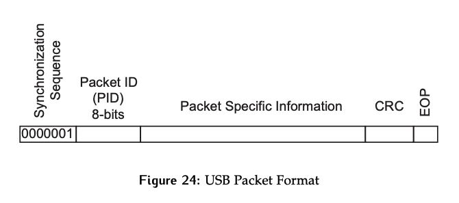
Packet-specific information is sent after the ID, followed by cyclic redundancy check (CRC) bits, which are the error detection mechanism, and finally the end of packet (EOP) sequence (two single-ended zeros). The format of the packet ID byte itself also serves as an error detection mechanism:
- The first 4 bits are the ID, and the next 4 bits are the complement or inversion of the ID.
- As a result, only 16 packet IDs exist.
Data Packet Types
USB data packets come in four flavors:
Interrupt – Because there are only 4 wires in the capable, there are no true interrupt capabilities in the sense of sending a signal on a dedicated line. Instead, if a device is interrupt based, something that is established during setup, then the root will poll it at regular intervals for new data.
- The device is able to dictate the required interval as part of the setup information. These transactions are time-sensitive to prevent data loss, and it is up to the root hub to make sure they get scheduled appropriately.
- This type of data packets is used to service USB devices such as keyboards and mice where only a small amount of data is transferred at a time, but losing it has serious system usability implications.
Bulk – As USB speed increased to make transferring large files practical, the supported size for these transfer was increased to 512 bytes per packet from 64 bytes. In the case of a file that is larger than 512 bytes, the file gets divided into as many packets as needed to send the entire file.
- This type of data packet requires that each piece of data must be delivered (prevent file corruption).
- However, there is no particular time constraint, so other packet types such as interrupt will be prioritized. The user is unlikely to notice and extra second or two copying a file, but they will notice is a keystroke from their keyboard is lost.
Isochronous transfer – Also added in USB 2.0 to accommodate high bandwidth transfers. There are some key differences between this type and bulk:
- Delivery is no longer guaranteed.
- Time sensitive.
- Supports a larger payload of up to 1024 bytes.
This is often used for things like streaming audio or video; if a packet is received with an error, its better to drop it and keep moving, than stall and wait for a resend. A small audio/video glitch is less detrimental than the longer pause required for a resend.
Control – These are used when the device is first connected to establish the device type and any configuration information the root hub will used to interact with it. The standard defines a series of profiles based on device types, such that a standard driver can be used; for example, keyboard, mouse, camera, USB stick, printer, etc. These pre-defined profiles and standard drivers are a key part of making devices plug-and-play, at least for basic functionality.
- If you plug in a keyboard with backlighting, the keyboard functionality will be available immediately, but you might have to install and additional driver to support the backlight features.
Example
Visualize a system that consists of a root controller and two devices that have already been setup as shown in Figure 25.
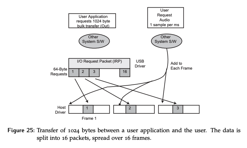
At this particular moment, one of those devices is receiving a bulk transfer of 1024 bytes, or an OUT transfer from the system perspective, while an audio device is requesting an isochronous stream at 1 sample per ms.
Assume the appropriate token packets have already been sent, and the data packet phase of the transaction is about to start. This is a USB 1.x system and can only send 64 bytes in the bulk transfer. As a result, the USB driver will divide the data into 16 data packets. If a newer version of the standard was used, only two data packets would be needed.
The host will be sending a SOF packet every 1 ms. Within each frame, each of the two devices is only allowed to interact with one packet. Thus:
- The first frame will have packet 1 of 16 from the bulk transfer, and an audio packet.
- Frame two will have packet 2 of 16 and an audio packet
- etc…