Major losses are the energy losses that occur due to friction within long, straight sections of pipe. This loss is influenced by:
- The length of the pipe ()
- The diameter of the pipe ()
- The velocity of the fluid ()
- The friction factor (), which depends on the pipe surface roughness and flow regime (laminar or turbulent).
The expression for major head loss is given by the Darcy-Weisbach equation:
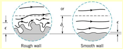
The roughness of the pipe surface affects the friction factor.
Minor losses are the energy losses associated with pipe fittings (elbows, tees, valves, etc.), sudden expansions or contractions, bends and junctions.
These losses are typically smaller than major losses but can accumulate significantly in complex piping networks.
The total head loss is given by:
Major Losses
Pressure Drop
The pressure loss is influenced by several parameters:
where is the surface roughness.
Alternatively:
- is the relative roughness, quantifying the effect of the pipe’s surface texture on friction losses.
- is the Reynolds number (Re), indicating flow regime
The pressure drop is proportional to the pipe length :
Friction Factor
As for the friction factor, we can consider the Darcy-Weisbach equation written in the form
is the Darcy friction factor, which depends on flow type and pipe roughness.
- For laminar flow (), the friction factor is simply . In this regime, surface roughness is insignificant because the viscous forces dominate
- For turbulent flow, the friction factor becomes complex and requires the Moody Chart or empirical equations for calculation
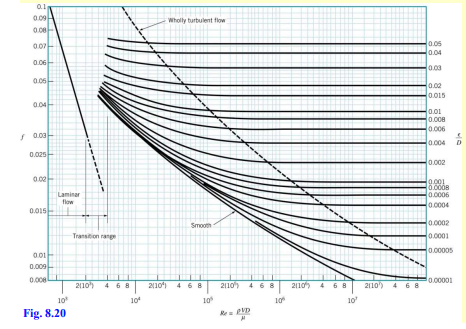
- Laminar region: Straight line showing
- Transitional region: Flow begins to fluctuate and turbulence starts
- Turbulent region: Characterized by curves representing different roughness values ().
The Colebrook-White Equation for turbulent flow allows us to find the friction factor in the turbulent region:
- This is an implicit equation – cannot be isolated directly, so it must be solved iteratively or read from the Moody Chart.
Head Loss Equation
The Darcy-Weisbach Equation can also be written in terms of head loss:
- Valid for fully developed, steady, incompressible pipe flows
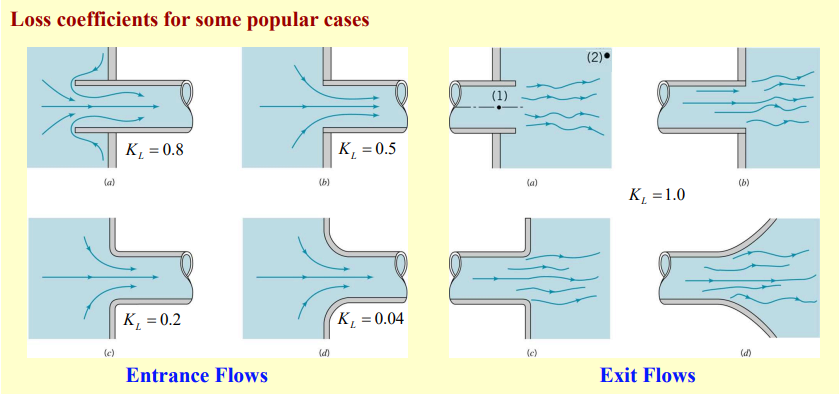
Minor Losses
Minor losses in pipe flow are associated with components and fittings rather than the straight sections of pipe. These include bends, valves, tees, expansions and contractions, entrance and exit points. Despite being called “minor,” these losses can add up significantly in complex piping systems, especially where many fittings are present.
Minor losses are quantified using the head loss equation for local disturbances:
These losses are modeled using a loss coefficient to encapsulate the effect of the disturbance:
is dependent on the shape and type of the components, as well as the Reynolds number and flow characteristics:
The pressure drop associated with minor losses can be written in terms of the loss coefficient: