Below we have the equivalent circuit diagrams of a DC generator and a DC motor.
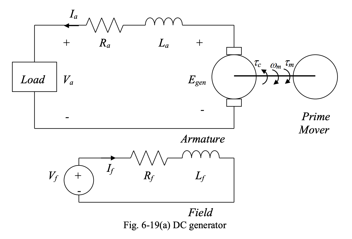
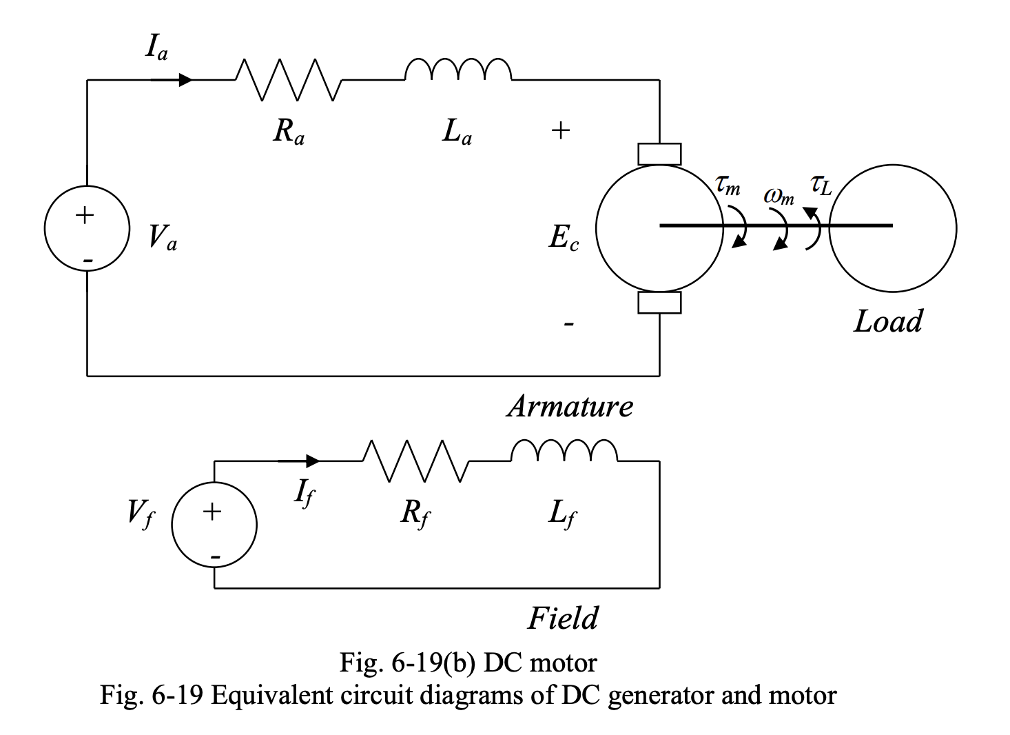
In the diagrams above:
- is the armature terminal voltage
- is the armature resistance
- is the armature inductance
- is the field winding terminal voltage
- is the field resistance
- is the field inductance
- is the armature current
- is the field current,
- is the developed toque in motor mode and the applied prime mover torque in generator mode
- is the load toque in motor mode
- is the counter toque in generator mode
- is the generated voltage in generator mode
- is the counter emf in motor mode
At DC steady state, the inductance behaves as a short circuit. The equivalent circuit diagrams above simplify to:
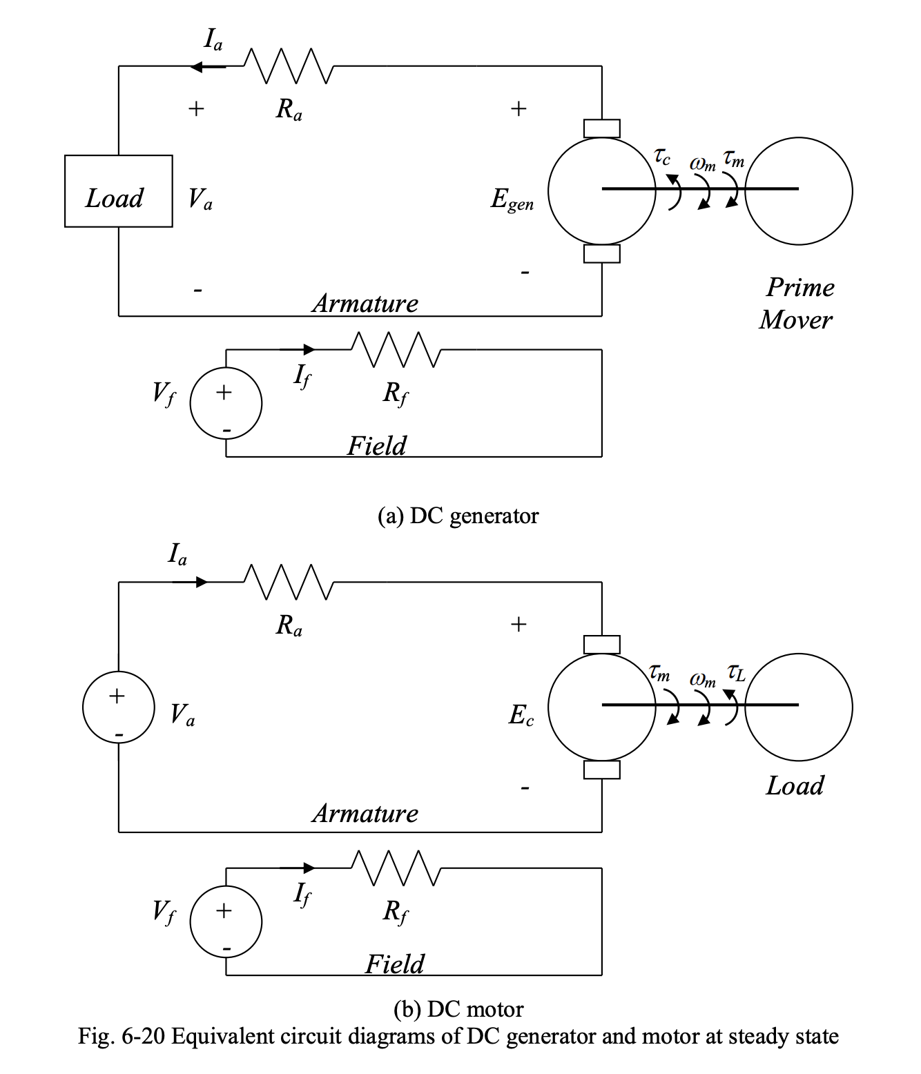
We have:
Note that is the number of turns of field winding.
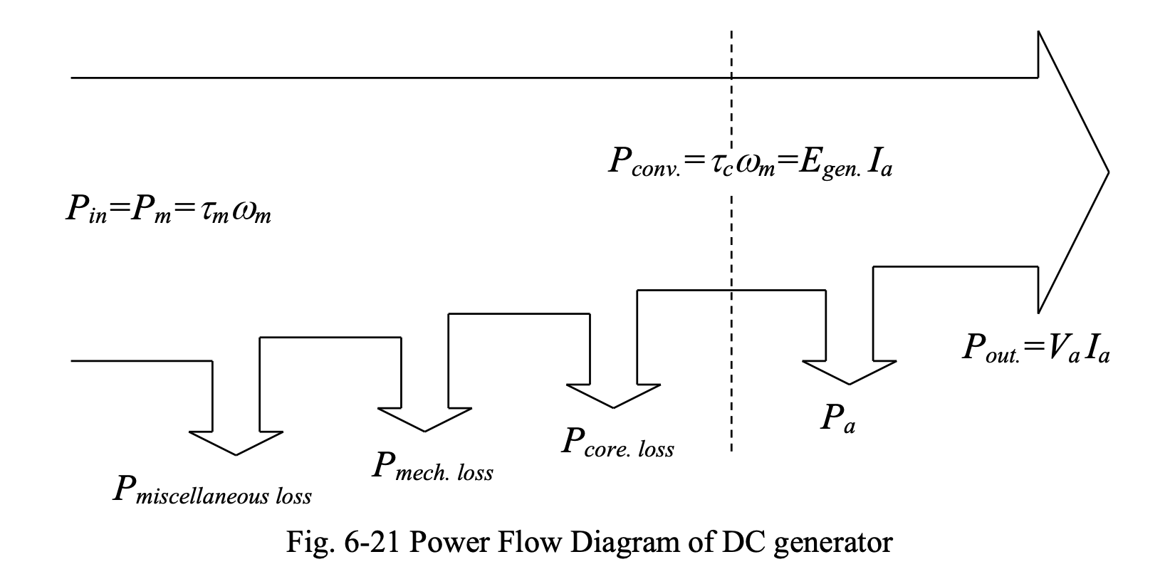
Power Flow of DC Generator
We have:
Thus, we have the following power quantities:
The above can be summarized by the diagram below:
Efficiency
The efficiency of the DC generator can be found based on the relations given above:
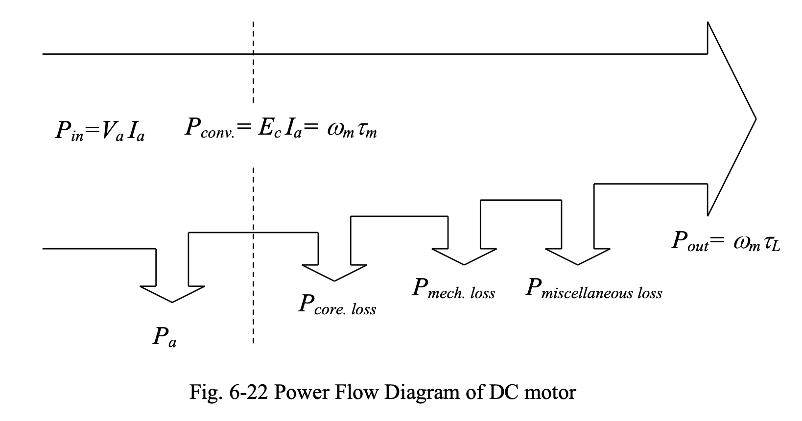
Power Flow of DC Motor
We have:
Then, we have the following power quantities:
This is summarized by the power flow diagram shown
Efficiency
The efficiency of the DC generator can be found based on the relations given above:
Improving Efficiency
To improve efficiency, DC machines are designed such that:
- Copper losses ( and ) are minimized by reducing and
- Core losses are minimized by using high-quality soft ferromagnetic materials (except in permanent magnet machines)
- Mechanical losses are reduced through good mechanical design
- Using a small reduces the voltage drop in the armature circuit.
In electric machines, the mechanical power is usually given in horsepower (hp), where .