TurtleBot
Odometry, mapping, and navigation from scratch
As part of ELEC 4260 (Intelligent Robots and Embodied AI) at HKUST, I implemented various functions for TurtleBot3 with ROS Noetic and C++, including:
- Odometry (wheel, ICP, EKF)
- Laser grid mapping
- A-Star Pathfinding
- PID control
- Exploration
Videos:
- Wheel odometry, mapping, ICP odometry (Real World)
- A*, PID, Exploration (Simulation)
- A*, PID, Exploration (Real World)
Wheel Odometry
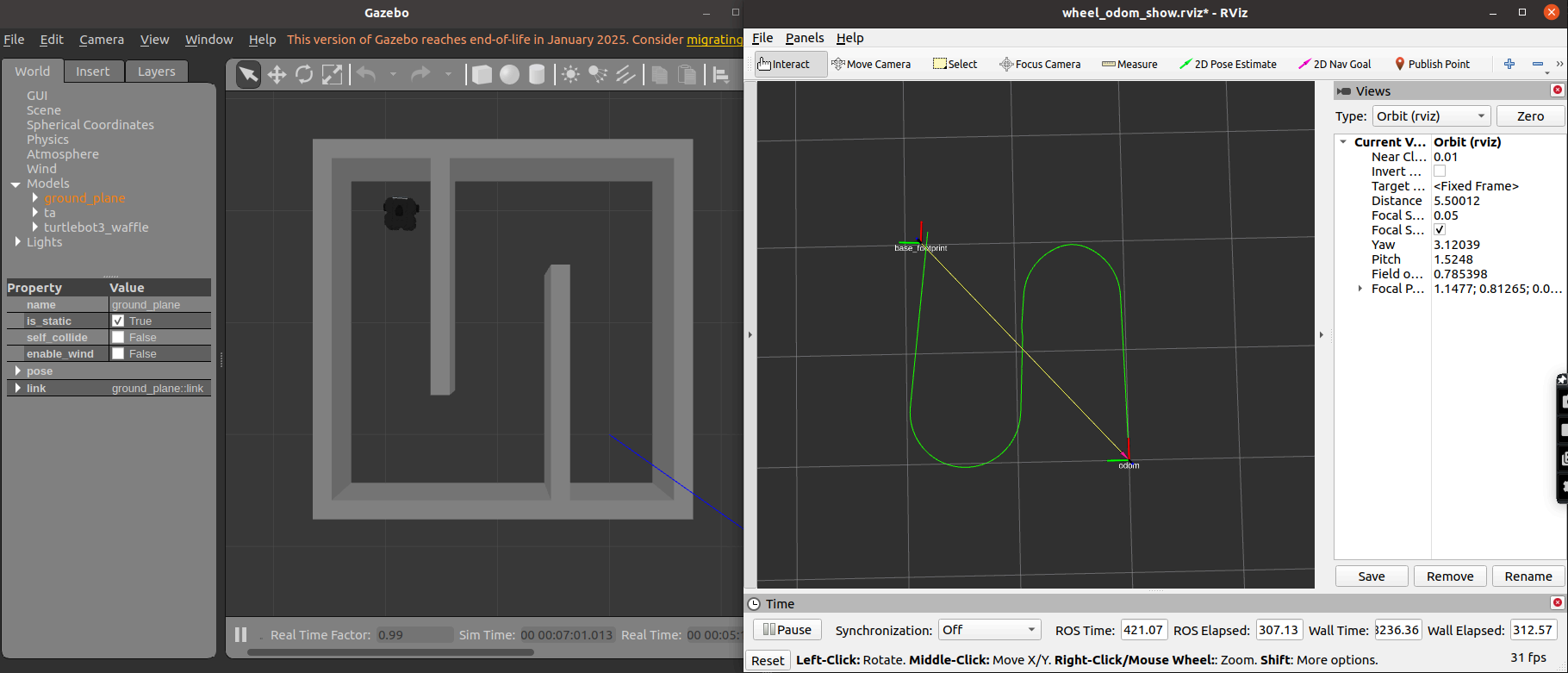
This node subscribes to joint state messages to obtain wheel rotations, computing the linear and angular displacement from the differences in wheel positions, and updating the robot’s global pose accordingly. The node then publishes both the updated path and odometry messages, including velocity estimates derived from time intervals between measurements.
Mapping
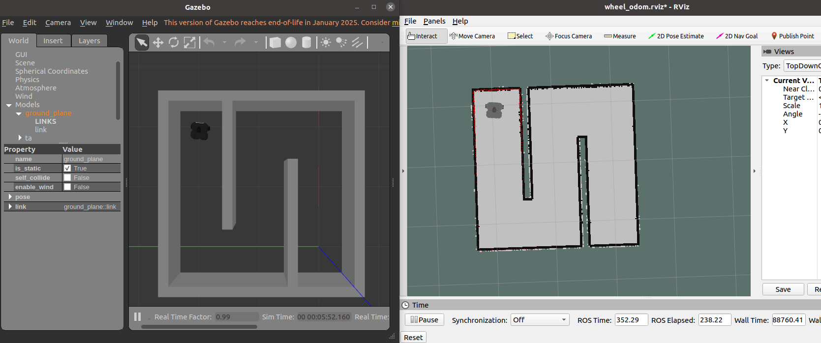
Laser scan measurements are transformed from the sensor’s frame into the map frame, aligning them with the robot’s base footprint and establishing a consistent spatial reference by initializing the map origin at the robot’s starting position. A Bresenham line algorithm is used to trace the path of each laser beam, updating cell statuses by incrementing scan counts for endpoints and applying a decay mechanism for free space. Cells are marked as confirmed once their scan count surpasses a threshold. Finally, the occupancy grid is published.
ICP Odometry
The occupancy grid map is turned into a point cloud by extracting cells that represent obstacles, and incoming laser scans are projected into the map frame. For each scan, the node transforms the laser data into a 2D point cloud using available tf transformations. Then, the ICP algorithm [2] is applied to align the current scan’s point cloud with the obstacle map cloud. This process computes the optimal rigid transformation by matching corresponding points and minimizing the alignment error through centroid computation, cross-covariance analysis, and singular value decomposition (SVD). The updated transformation is broadcast as a new map-to-base transform, and an odometry message reflecting the refined pose is published.

EKF Odometry
I implemented an Extended Kalman Filter to use wheel odometry for motion prediction and refine it with ICP odometry corrections to improve localization accuracy. This takes advantage of high-frequency updates from wheel odometry and global corrections from ICP, while compensating for accumulating drift from wheel odometry, and slow speed from ICP. I found that this method functions much faster than just ICP, but still had occasional accuracy problems and inconsistent covariance.
A-Star Pathfinding
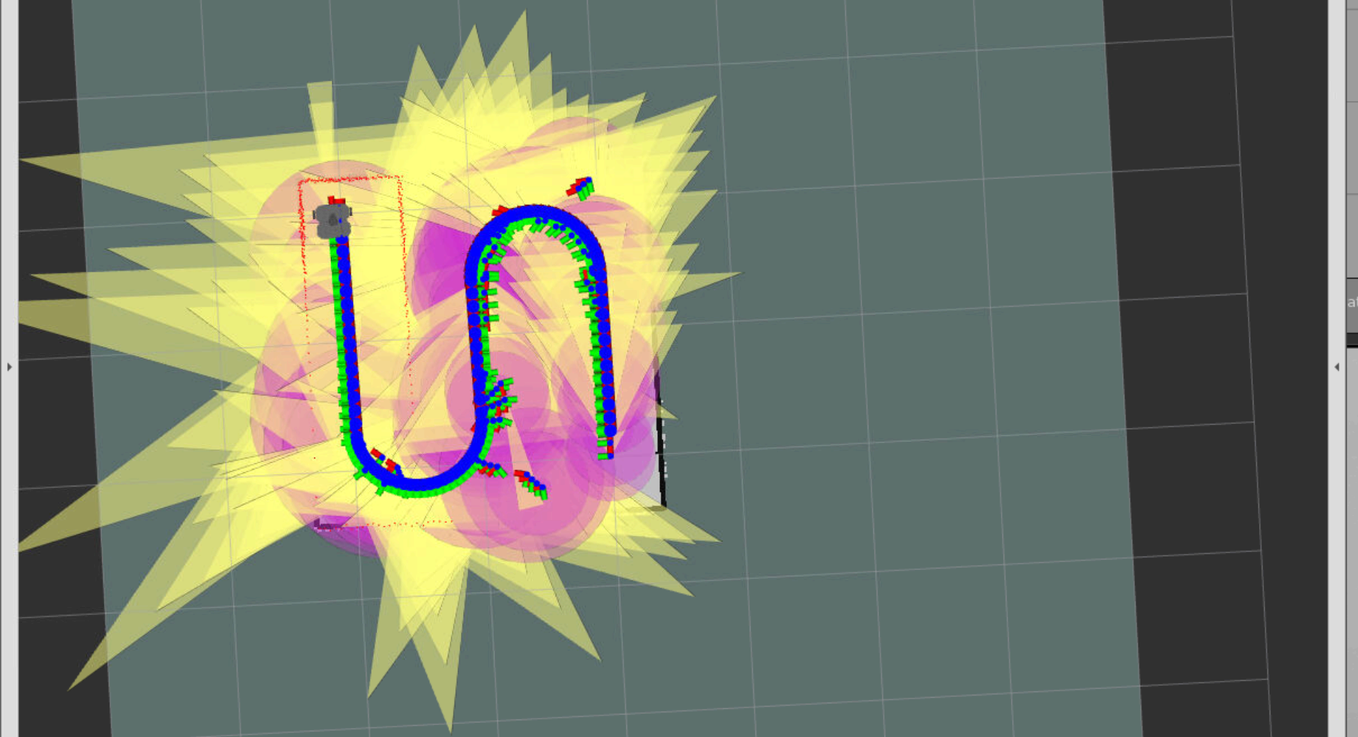
The A* node performs obstacle inflation based on the robot’s radius to ensure safe navigation and computes the shortest path from the robot’s current position to a goal using the A* algorithm. The raw path is then smoothed using cubic Bezier curves after uniform sampling to generate a more navigable trajectory. The node subscribes to map and goal topics, and publishes both the raw and smoothed paths, as well as the inflated map for visualization.
PID Controller
The PID controller node implements a path follower for the mobile robot using a received global path and odometry feedback. It continuously computes the distance and heading errors relative to the current path waypoint and applies PID control to generate velocity commands (cmd_vel) for smooth and accurate path tracking. The controller automatically stops the robot upon reaching the final goal within a specified tolerance and publishes a goal status flag.
To see PID performance, see simulation and real-world videos.
Exploration
The exploration node uses a frontier-based exploration strategy; upon receiving an occupancy grid map, it inflates obstacles according to the robot’s radius, identifies reachable areas, and detects frontiers (regions between known and unknown space). It clusters these frontiers and selects the largest cluster’s centroid as the next navigation goal, publishing it, which enables the robot to use A* to find a path and PID to follow the path.
Improved Mapping for Real-World
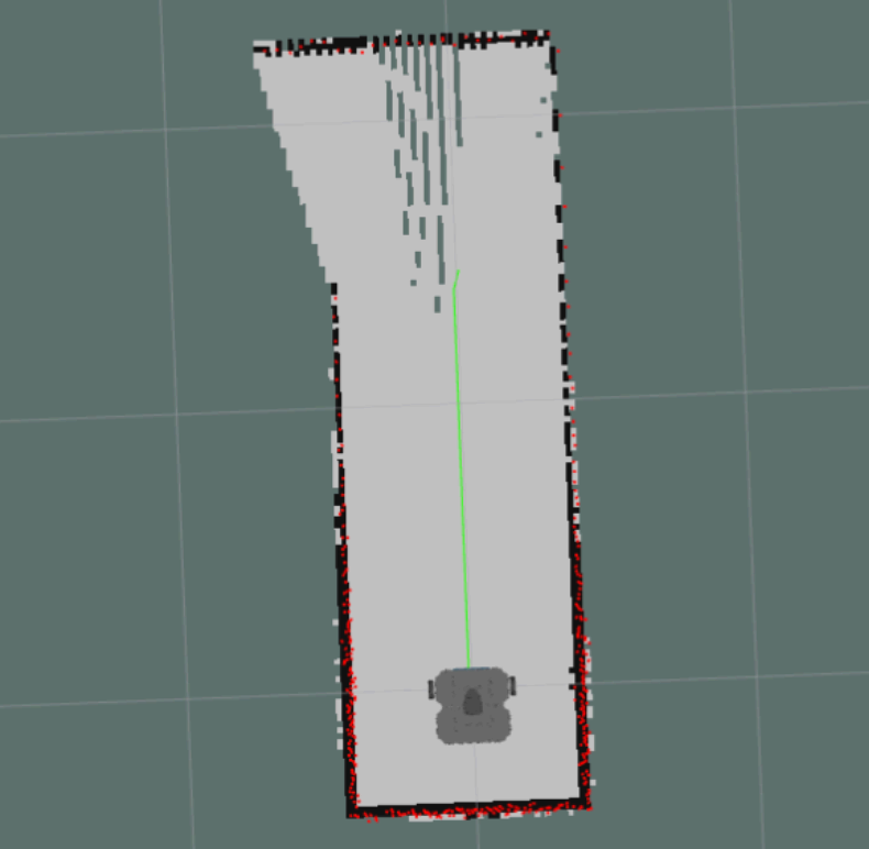
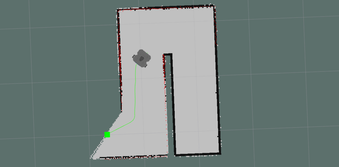
A significant issue with transferring from simulation to the real world was higher noise in the mapping node, which caused that exploration node to fail at times. Specifically, gaps in the maze walls would cause the mapping node to detect freespace outside of the maze, leading the robot to attempt to explore this freespace with no viable path. See the image below for an example of this.
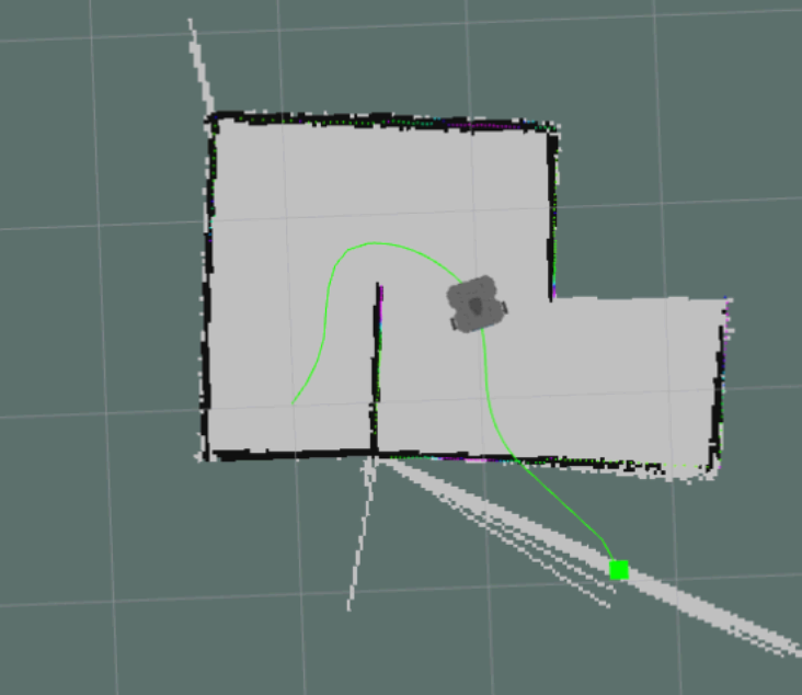
Thus, in order to improve the performance of the robot in the real world, I created an improved version of the createmap node more suitable for the real world using filtering and validation mechanisms. This includes:
- A function filter out laser scan rays that are significantly different from their neighbors, reducing false positives in obstacle detection.
- A function to confirm obstacles only when they are surrounded by a certain number of other obstacles, enhancing the reliability of obstacle confirmation.
- A function for adjustment of wall thickness to close small gaps.
Another alternative solution would have been to add a heuristics or path validation steps to prevent the robot from attempting to explore areas that are disconnected from the current known map, or altering the inflation logic to be more aggressive. In general, I believe my approach of cleaning up the map is the most scalable.