Turning my iPhone into a robot
The chronicles of roamr
As part of the UWaterloo Engineering undergraduate program, students complete a capstone design project. With my teammates Anders, Nathan, Olivia, and Thomason, we conceptualized and built roamr, an iPhone-based autonomous mobile robot (AMR). This post details roamr’s long journey from its inception to its current state; instead of introducing the final design right away, I walk through the design process we went through for each subsystem.
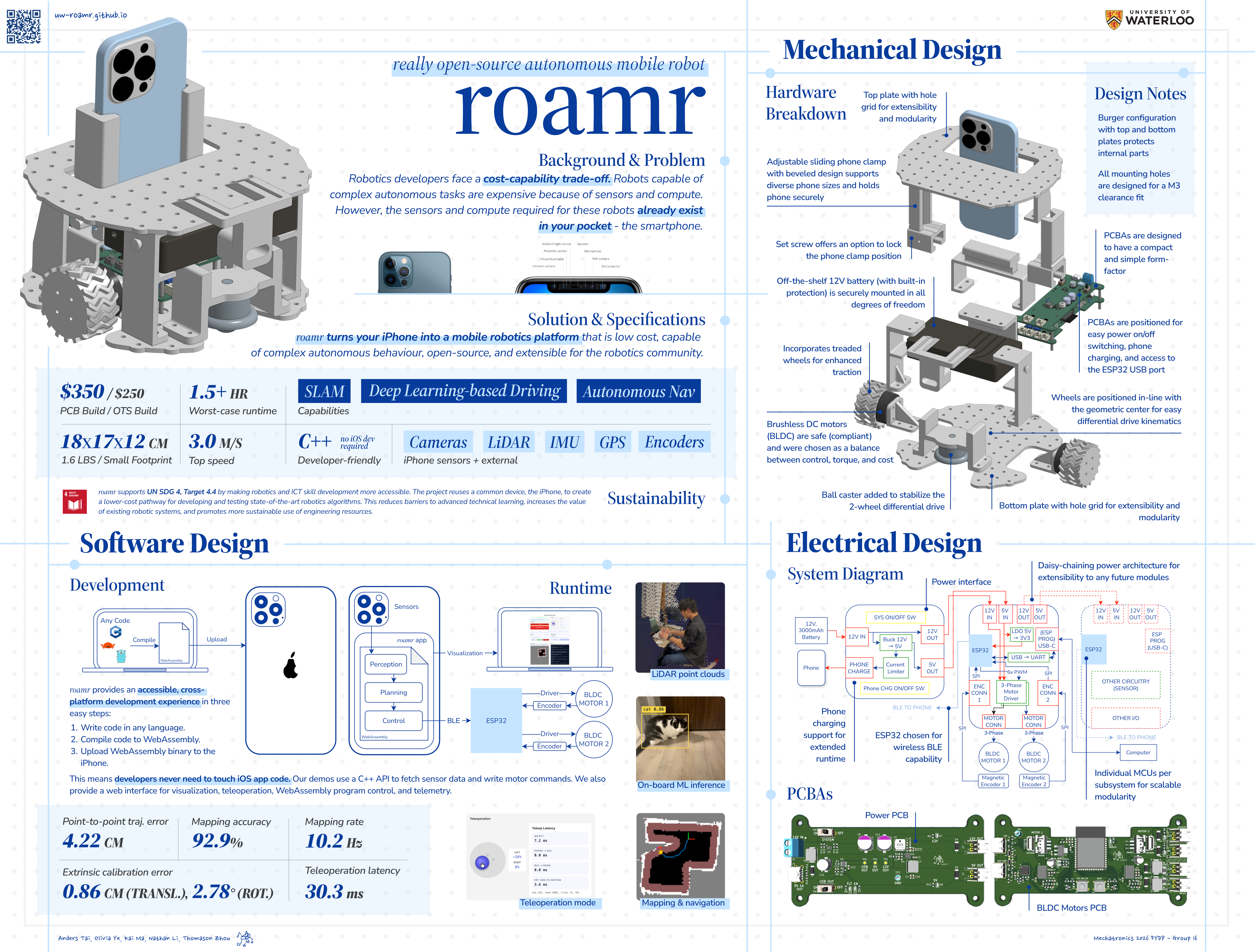
If you want to build your own roamr, please visit the roamr website where we have everything you need.
Motivation
Have you ever wanted to build an autonomous mobile robot? Most people have played with mobile robots in some form; any vehicle capable of locomotion could be considered one, like RC cars. But making it autonomous is an entirely separate matter — an AMR requires considerable sensing capabilities to perceive its surrounding environment, as well as enough computing power to process this information and make an informed decision. A good example of a basic task that we would want an autonomous robot to be capable of is mapping and navigation. That is, given an unfamiliar environment, it should be able to identify obstacles or objects, drive around obstacles to get to new locations; this also requires the ability to localize (figure out where it is on the map), or at the very least odometry (track its motion relative to its starting point).
Because of the sensing and compute capabilities of AMRs, they tend to be quite expensive. TurtleBot has long been one of the most popular AMR platforms for research and education; the newest iteration, the TurtleBot4, is a whopping \$3000 CAD! Even platforms that are far less capable, like LEGO robots, are easily hundreds of dollars; the current iteration of LEGO robotics, the SPIKE, is around \$600 CAD.
How do we go about alleviating this problem? Recall that the important (and expensive) parts of an AMR are sensing and computing power. The average consumer actually already has these readily available in their mobile device; your average phone is a fairly capable computing device (the Apollo 11 mission ran with much less power), and has a respectable set of sensors. Thus, our idea was to build a platform that would use a phone for sensing and compute, making the cost much lower. We decided to use the iPhone due to its dominant market share in North America (and everyone on the team had an iPhone). We also hoped to capitalize on the fact that Apple had recently made substantial investments into sensing hardware for AR/XR applications, many of which would translate well to robotics, such as the LiDAR on iPhone Pro models.
Our synthesized goals for the project were thus to build an AMR platform that is:
- Low-cost (by leveraging the iPhone for sensing and compute)
- Capable of complex autonomous tasks, appropriate for research use
- Open-source, so that anyone can improve on our work
- Extensible to further applications in the future
Around these core goals, we came up with additional specific constraints and requirements, summarized below:
Constraints
| Category | Constraint |
|---|---|
| Cost | Total build cost must be < $500 (excluding the cost of the iPhone). |
| Phone Integration | The final solution must utilize onboard iPhone sensors (camera, LiDAR, IMU) and process the data on the iPhone. |
| Open-Source | All hardware and dependencies must be open-source; must not rely on closed-source software or proprietary parts. |
| Interfaces | Interfaces are abstract, with at least one concrete example implementation. |
| Durability | Must withstand impacts with a wall at 3 m/s without loss of function. |
| Cycle Time | Must run for at least 30 minutes per battery charge, not including the iPhone charge. |
Objectives
| Category | Objective |
|---|---|
| Weight | Target weight under 5 lb (excluding phone) for easy handling; lighter is preferred. |
| Size | Must fit inside a small backpack (approx. 45 × 35 × 30 cm); more compact is better. |
| Mobility | Capable of climbing slopes up to 15°. |
| Modularity | Support for add-on modules (e.g., arms, legs, sensors) to enable research flexibility. |
| Robot Capability / Software | - Point-to-point navigation (accuracy < 10 cm) - Absolute trajectory error < 10 cm (in controlled environments) - Built-in safety (collision avoidance): Must detect and avoid obstacles > 5 cm - Mapping: Maintain and update local map at ≥ 5 Hz, with resolution < 5 cm per cell (for grid mapping) - Teleoperation: Remote driving with latency ≤ 150 ms - Extrinsic calibration: < 1 cm translation error, < 5° rotation error - Support for learning-based autonomy (e.g., end-to-end driving) - Support for SLAM (with pose & landmarks) |
Mechanical
Preliminary concepts and designs
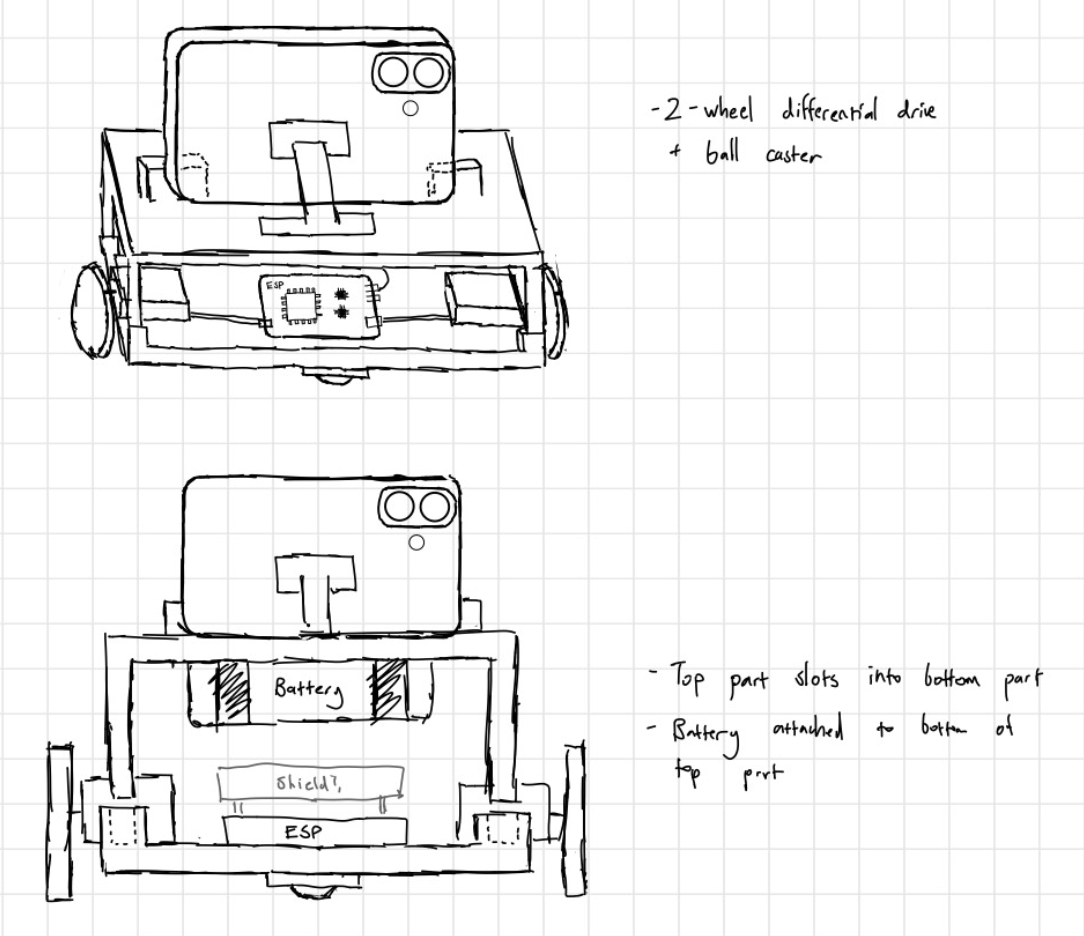
We first came up with some concept sketches (one is shown below) of how we wanted it to look and function mechanically. The general idea was to have a 2-wheel differential drive configuration, with a ball caster for stability; this would let the robot be user-friendly (simple kinematics to program) and minimize the number of motors, keeping the cost low.
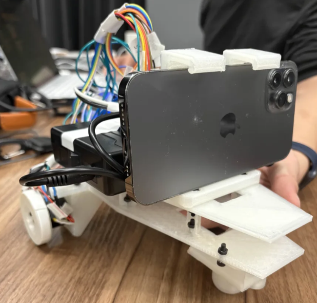
roamr v1 prototype
The concepts that we came up with were evaluated with respect to our goals, constraints, and requirements. The winning concept, with slight tweaking to make everything work more smoothly, was implemented in CAD.
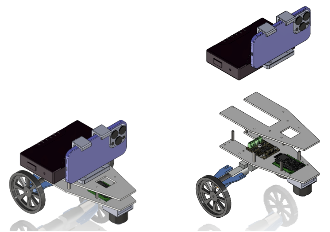
To verify the real-world functionality of our mechanical and hardware designs, we constructed a fully operational prototype—roamr v1. Building this prototype enabled us to rigorously test and validate a wide range of our physical constraints and objectives. For example, assembling and running the robot gave us direct feedback on its structural durability, weight distribution, and balance, as well as the ease of integrating major components such as the motors, electronics, chassis, and phone mounting system. This process also highlighted which design decisions worked as intended and revealed practical issues, surfacing areas for refinement.
Final design
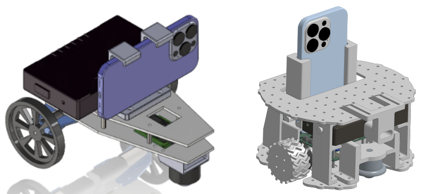
While the roamr v1 prototype showed that our core design was viable, there was obviously lots of room for improvement. Led by Anders and Nathan, we made various modifications for the final design (roamr v2), listed below:
- Phone stand: Instead of the awkward fixed clamp, we added a sliding mechanism that allowed for adjustable clamping with much better ease-of-use.
- Phone configuration: Originally, we had the phone horizontally, as this provided a wider field of view. However, we realized that both the horizontal and vertical configurations had relatively narrow field of view, and either way we didn’t have 360-degree LiDAR; thus, both configurations would need to turn to do a 360 scan. The vertical configuration allows for easier access to the phone app screen and reduces the robot size, so we switched.
- Wheel location: Both designs used two-wheel differential drive with a ball caster to provide support and stability. However, in the final design, the wheels were placed in the geometric center of the robot to allow for turning in place. Furthermore, the motors were moved closer together so that less torque would be required to turn the robot (smaller moment arm).
- Chassis: The original chassis didn’t protect the battery (in fact, we just secured it with duct tape). The final design was expanded to both protect the battery and also allow easier access to electronics, along with more mounting holes for flexibility and extensibility.
- Battery mount: We added a full top and bottom battery mount to hold the battery securely but also allow it to be removed easily (sliding lock mechanism) for recharging.
Electrical
General architecture and component selection
Hardware design, led by Olivia, began by outlining a high-level concept for the architecture (see the block diagram below) and identifying the communication protocols to use. The plan involved developing a roamr app for the iPhone, which would transmit commands to an ESP32 microcontroller via Bluetooth Low Energy (BLE). The ESP32 would then handle motor control. Because the robot is mobile, the entire system would draw power from a wireless power system — a battery.
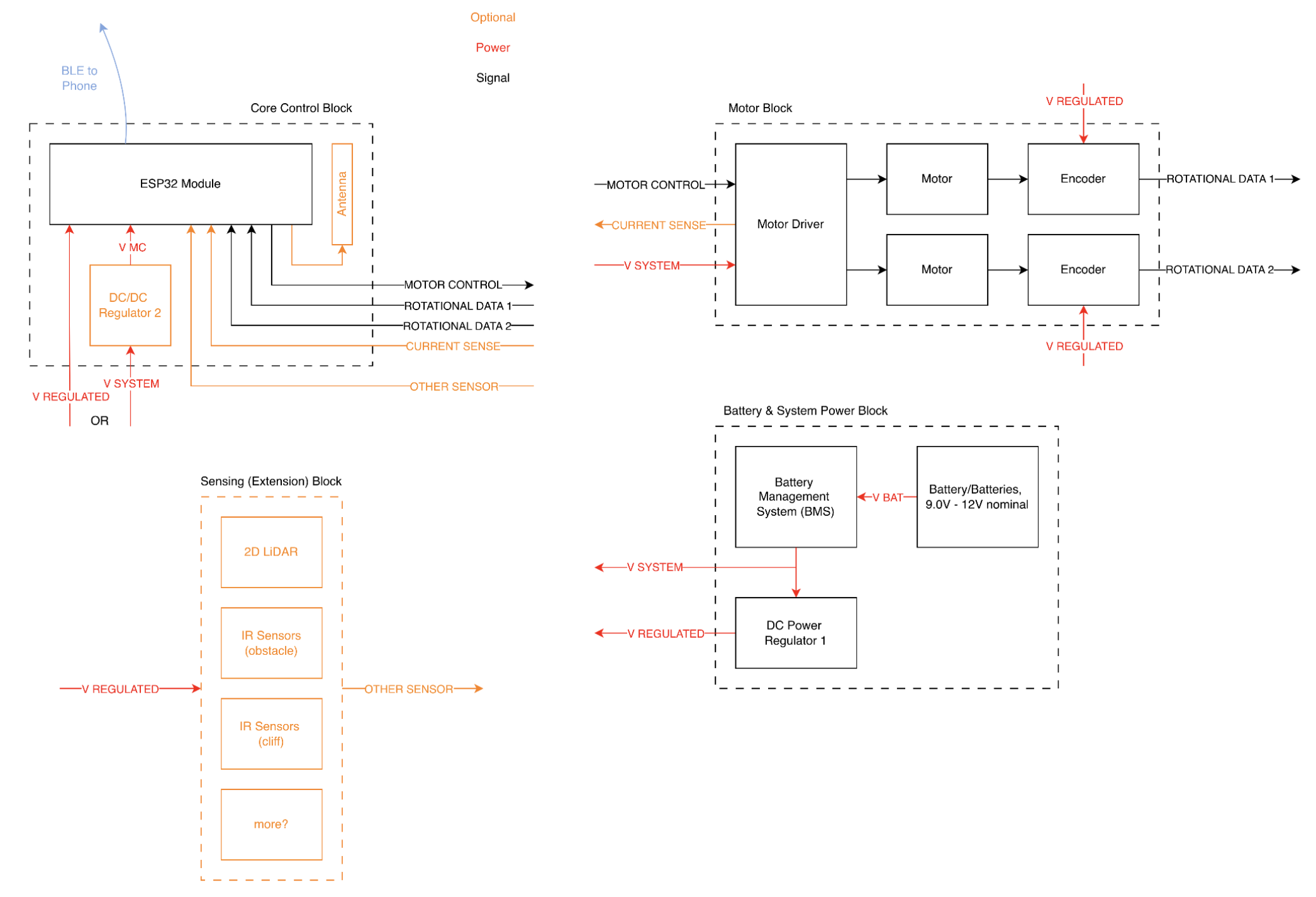
To select our hardware components, we started with our key robot specifications—such as runtime and maximum speed—and worked backwards from there. We calculated the necessary torque, power, and current for each motor based on factors like the robot’s maximum weight and its ability to climb inclines, ensuring that the projected current draw remained practical. Based on these requirements, we chose a 12V 3000 mAh battery and selected BLDC motors that struck the right balance among torque (at least 0.5 Nm), speed (at least 72 RPM), affordability, and safety.
As part of the roamr v1 integration test, we realized the hardware design with off-the-shelf components (power regulator modules, ESP32 development modules, and motor driver modules) and hand-soldered wires to create a rapid prototype. After confirming that the basic design was valid (able to control motors as desired), we moved on to refining it for the final design.
Upgrading to PCBs
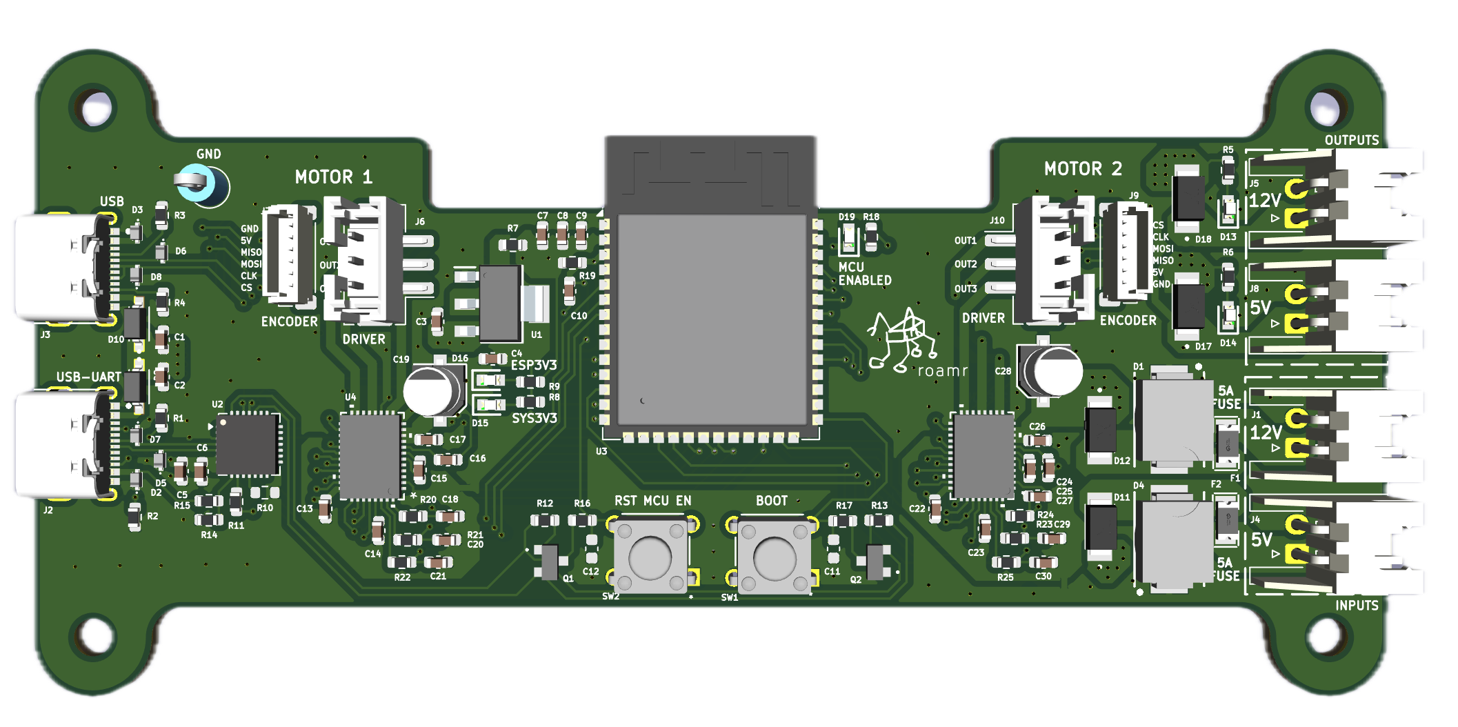
We eventually switched from off-the-shelf components to a custom PCB (definitely not designed and manufactured very last minute) that would allow us to realize a more modular electrical architecture, along with obviously better aesthetics. This consisted of a motor PCB and power PCB; see the new and improved architecture in the diagram below.
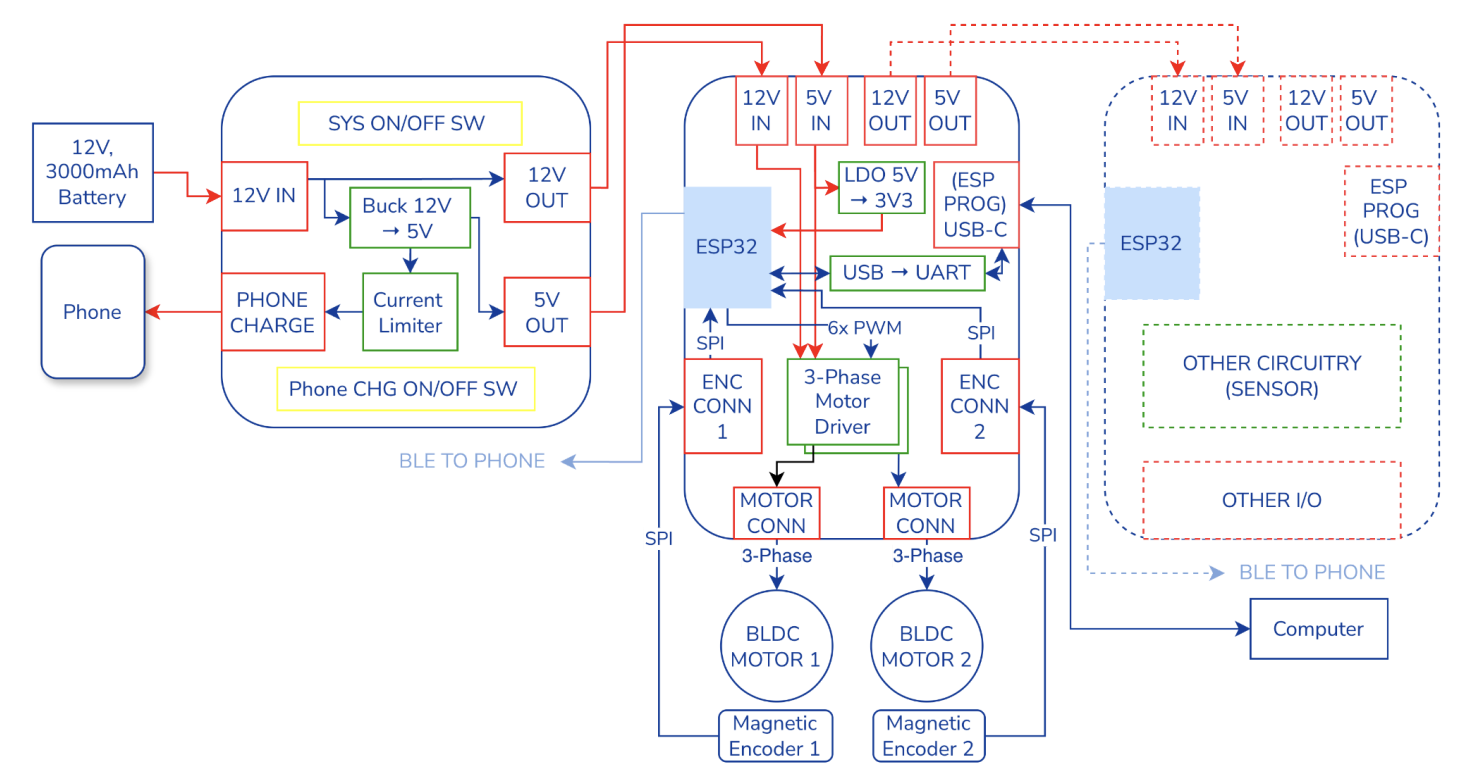
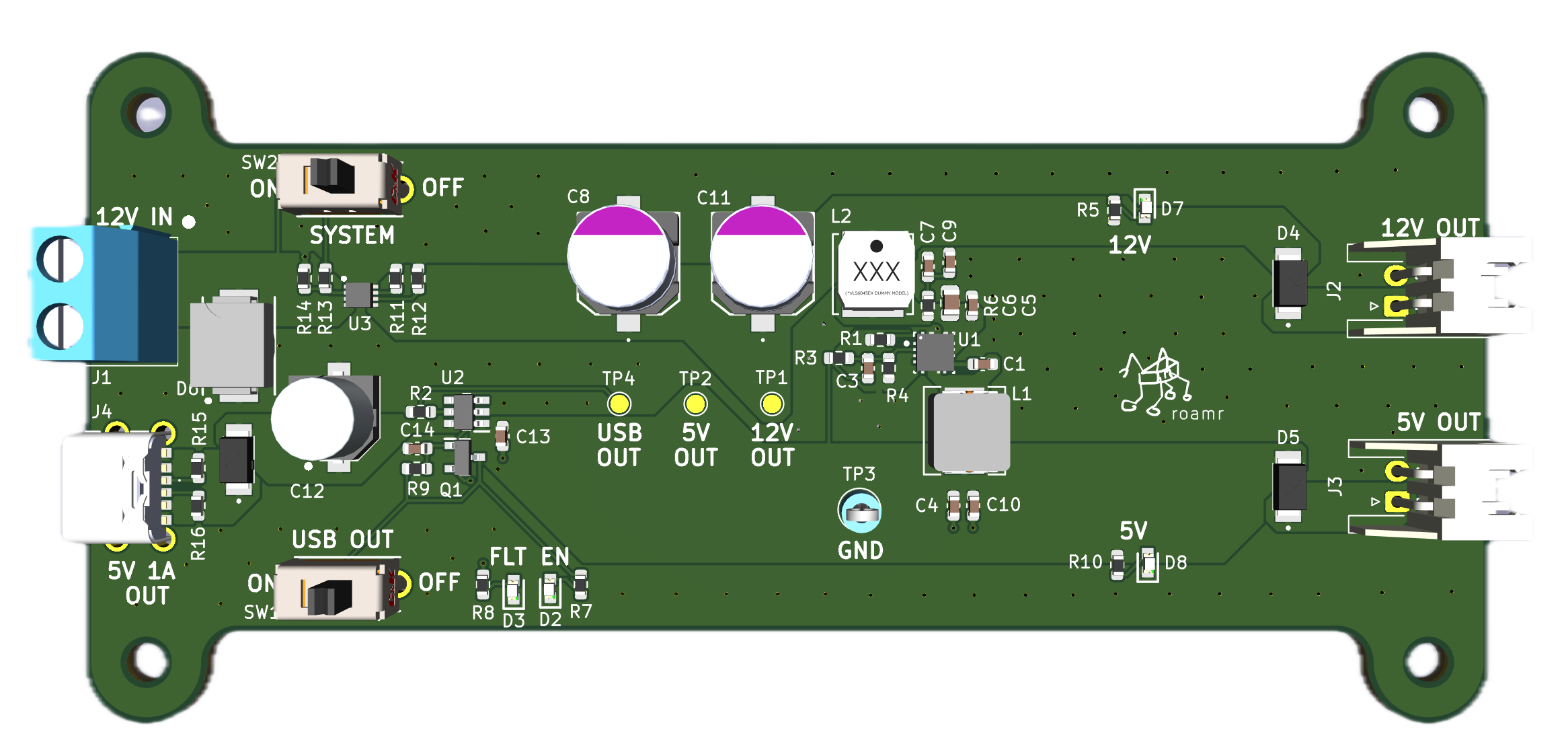
The power PCB served as the main interface between the battery and the rest of the robot’s electrical system. It accepts a 12V battery input and provides a direct 12V pass-through for modules and subsystems that require full battery voltage. It also steps the 12V input down to 5V for lower-voltage electronics. Finally, it supports USB-C phone charging at the USB default current of 500 mA.
The motor PCB gets both 12V and 5V lines coming in from the power PCB. The 12V mainly powers the three-phase motor drivers, while the 5V goes to the encoders, and is also dropped down to 3.3V with an LDO for the ESP32 and off-board encoders. For communication, SPI is used; the ESP32 communicates with both the motor drivers and the magnetic encoders over SPI. There’s also a USB-C port for connecting the ESP32 to a computer (for things like flashing firmware or monitoring), with a USB-UART bridge making the actual connection work behind the scenes.
We used field-oriented control (FOC) to drive the motors, since it works especially well with brushless DC motors and offers smooth, precise, and reliable closed-loop control. To keep things simple and accessible, we went with the SimpleFOC library, which is popular among hobbyists. For precise feedback, we paired this setup with 14-bit AS5048A absolute magnetic rotary encoders, making sure the control loop could stay as accurate as possible.
Software
Software for roamr was a surprisingly complex issue and required a fair amount of innovation on our part to get to a nice design.
To see why this is, recall that we wanted roamr to be capable as a research platform; thus, researchers/programmers should be able to program the robot however they see fit. This is not easy because roamr’s main device is an iPhone, which is not exactly famous for being a very hackable platform where programmers can run arbitrary code. While we do have an ESP32 microcontroller onboard, this is nowhere near powerful enough to handle complex sensor processing pipelines, especially with images and LiDAR data. Upgrading to something more powerful, like a Raspberry Pi or a Jetson, would drive up the cost and waste a bunch of available phone processing power. Forwarding the data to another device like a PC would also be less than ideal for similar reasons.
Moreover, how users program roamr matters. The most natural way to access and interface with the sensors is to write an iOS app; however, we don’t want users to have to do any mobile iOS development. It would be annoying for users to have to learn an iOS-specific language like Swift, and even more annoying for users to have to re-build and download a custom app through Xcode every time they want to make the robot do something different.
To address these problems, we came up with an architecture that is split between the sensing/compute host (iOS) and the motion actuator controller (ESP32), with a sandboxed WebAssembly (WASM) runtime inside the iOS host for user development.
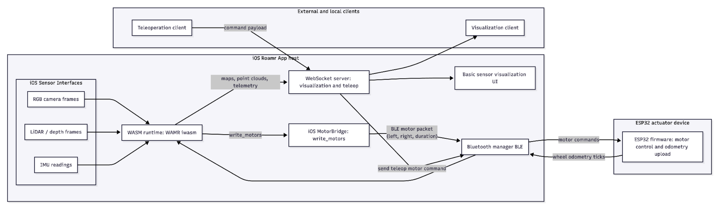
The roamr iOS app collects sensor data using iOS APIs and passes it to a WebAssembly (WASM) runtime, where the main autonomy code runs. At the same time, the app communicates with the ESP32 over Bluetooth (BLE) to send motor commands and receive encoder feedback. Users can write autonomy code and compile to WASM, using sensor and encoder data to make decisions, producing map and telemetry data (sent out by iOS via websockets), and generating motor commands (sent back to the ESP32 over BLE).
iOS App
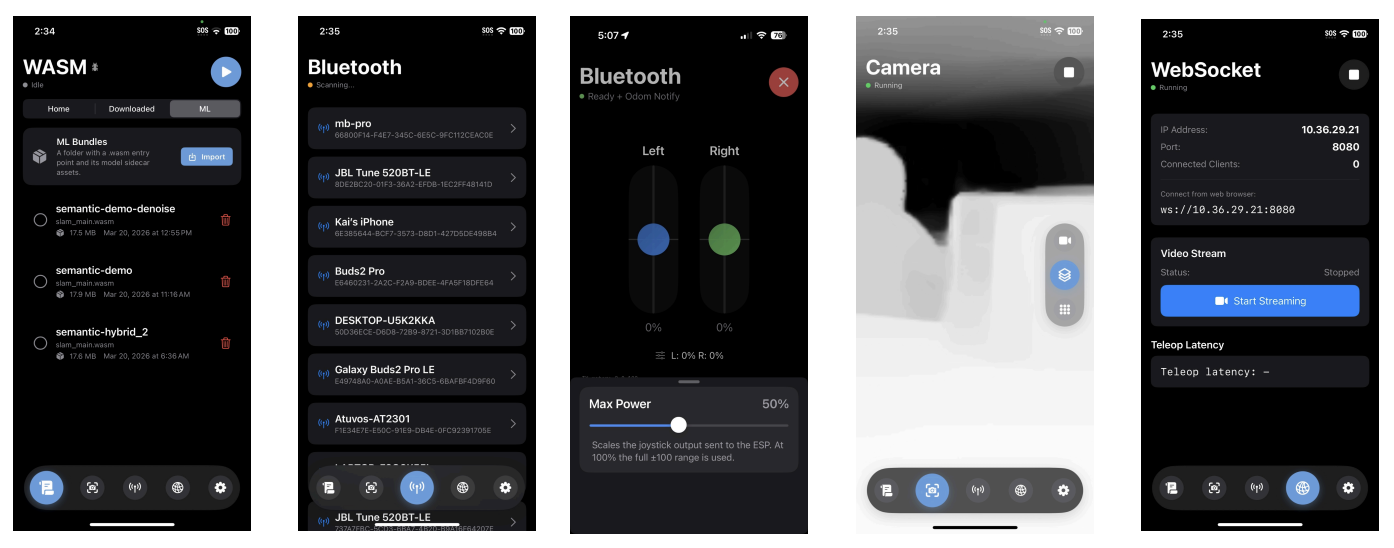
The roamr iOS app, shown below, serves as the primary interface for accessing sensor data and running code. It coordinates with the ESP32 microcontroller to write motor commands and read encoder feedback, and executes sensor/robot processing logic via an embedded WebAssembly (WASM) runtime, and providing real-time visualization and teleoperation capabilities through a websocket-based interface.
WebAssembly runtime
The app hosts a WebAssembly (WASM) runtime, which makes it so that developers can write and upload guest code that gets run by the app without having to re-build or download a new app. Specifically, they can write any code that processes sensor streams and issues motor commands; this is compiled to WASM and run on the phone with WAMR (WebAssembly Micro Runtime). We picked C++ for the guest code language because it’s commonly used in robotics, but any language that can be compiled to WebAssembly can be used.
Notably, the WASM module doesn’t own the camera, LiDAR, or motors directly; it talks to the world through a narrow host boundary, with imported functions for sensor reads and motor writes, UI-driven hooks, etc. This split is intentional, such that the user’s guest code is just focused on autonomy algorithms and state machines, while the iOS host handles timing, permissions, device drivers, and forwarding motor commands over BLE.
Guest code calls the host through imports that look like ordinary C++ functions. The implementations for these functions live in the iOS app, with headers that annotate them with WASM_IMPORT so the linker binds them to the embedded runtime. For example, consider the following code example below: we obtain IMU samples by filling an IMUData struct — allocate it, call read_imu, then read the accelerometer, gyroscope, timestamp, and coordinate-frame.
#include "sensors/imu.h"
void poll_imu_example() {
  sensors::IMUData imu{};
  sensors::read_imu(&imu);
  // imu.timestamp, imu.acc_*, imu.gyro_*, imu.frame_id
}
Reference type definition:
struct IMUData {
  double timestamp;
  double acc_x, acc_y, acc_z;
  double gyro_x, gyro_y, gyro_z;
  core::CoordinateFrameId_t frame_id; // 0=RDF, 1=FLU
};
WASM_IMPORT("host", "read_imu") void read_imu(IMUData* data);
Autonomy demo
To show how everything works together, we built a demo where roamr maps and navigates a space on its own. The system makes a 2D map using LiDAR, tracks its position with wheel encoders and IMU, plans paths to unexplored areas, and follows those paths. A state machine manages steps like planning, scanning, and following paths. Instead of one big loop, different parts of the system share key data like the pose, map, LiDAR scans, and planned path. This keeps things simple and modular, letting parts run independently but still coordinate smoothly.
The robot estimates its position using wheel odometry for movement and IMU measurements for orientation. These estimates are continuously combined into a shared pose. A short history of previous poses is maintained so that LiDAR measurements can be matched with the robot’s position at the time they were captured.
LiDAR data is collected independently from the mapping process, allowing sensor acquisition and map updates to run without blocking one another. The mapping system filters and simplifies each LiDAR frame before using it to construct a local 2D occupancy map of free and occupied space. Updated map information is then shared with the planning and visualization systems.
The robot’s possible operating states are summarized in the state diagram shown below.
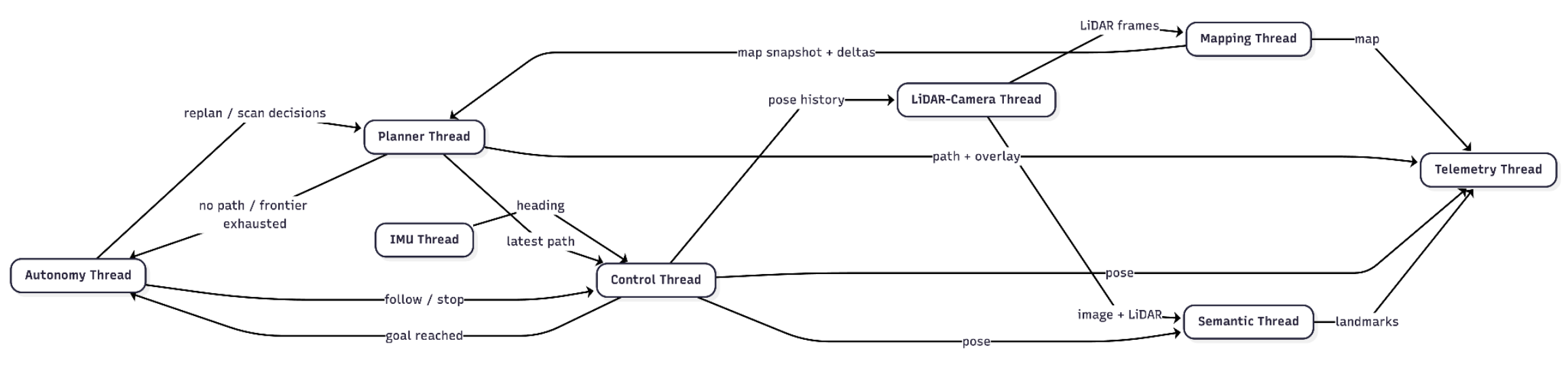
The path planner uses the map to identify unexplored regions and generate collision-free paths toward them. It updates the current path when newly detected obstacles affect the robot’s route. The control system follows these paths using feedback from the robot’s estimated position and wheel motion. At each destination, the robot performs a full rotation to observe its surroundings and update the map before continuing.
Later on, we added an ML portion that enables semantic mapping runs alongside navigation. Camera detections from a pre-trained SSDLite320-MobileNetV3-Large model are combined with LiDAR measurements to estimate the real-world locations of recognized objects. Repeated observations are merged to produce more stable object locations over time.
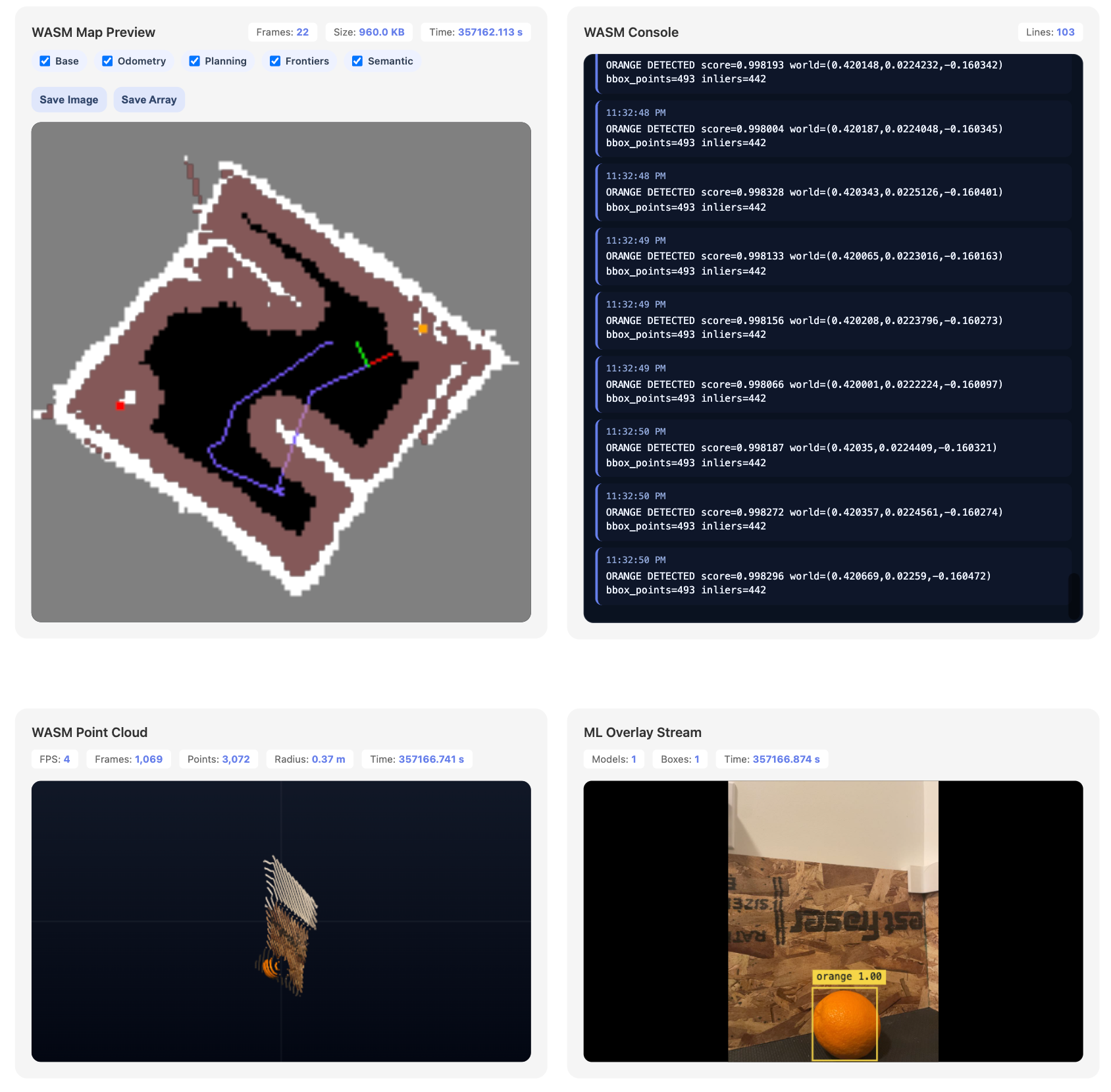
Telemetry and data recording operate independently from the main mapping and control systems. The visualization interface displays the robot’s map, trajectory, planned path, and detected objects in near real time without interrupting navigation. It also allows the user to stop autonomous operation and control the robot remotely.
What’s next for roamr?
roamr was successfully showcased at the 2026 Waterloo Engineering Capstone Symposium, but that doesn’t mean its journey is over. I think that there are still lots of fun things to work on. Some specific ones I want to try:
- Implementing a proper SLAM system on roamr. The above autonomy demo is not doing actual loop-closure and just relying on odometry for localization.
- Legs? Arms? The hardware is architected such that other components should be easy to add, but we never got to try adding more stuff. This could also be sensors, etc.
- End-to-end NN driving and fleets. OpenBot, another phone-based robot, showcased some interesting projects using end-to-end neural networks to drive, as well as doing collective learning with fleets. Why not try the same with roamr?